
Record two marks together at each inside corner: the material left in the corner and any bright trace on the adjacent face. On a long straight run, compare the middle of the span between supports with the edge near a support. These paired checks help distinguish a clearance problem at the turn from a locating problem along the frame.

The frame-grinding footage shows a covered arm carrying a long rectangular frame to the work surface. In the wider view both arms are visible, with sparks at the worktable contact area. This is the part of the operation where a trial should show which edge is being worked and which surface must remain intact.
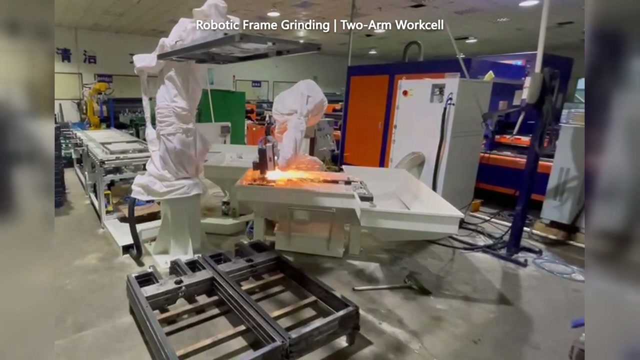
00:54 in the video. Sparks at the worktable contact area as both robots are visible beside the long frame.
Put the defect on a drawing
Before a trial, outline the material to remove and the adjacent surfaces to keep. On a straight run, inspect midway between supports as well as near the ends. If a missed band changes when the frame is reseated, check workpiece support and the locating points before compensating in the robot program.
At a transition or an inside corner, check the approach and exit against the visible marks. A corner may retain material if the abrasive cannot enter at the right angle. A bright mark beyond the target can indicate contact on the adjacent surface while the tool turns. Use a representative joint or corner to see whether a separate pass, a different working angle or another tool should be included in the trial.
Keep the worn-tool frame
Some compliant grinding tools accommodate surface variation through controlled travel and can report position changes associated with abrasive wear. A signal is most useful if you can connect it to changes on the finished frame. Save a frame produced early in the abrasive’s service life and another from near the planned change, using comparable blanks. Inspect both across the same marked regions. If only the later frame shows leftover material, verify the change interval and trial conditions before adding an extra pass to every frame.
For acceptance, keep photos that show the boundary between the target and protected surface and record the abrasive condition alongside each one. Discuss your frame trial with EVST using a full-part photo and paired photos of both faces at the same corner, plus readings from the middle and end of the longest unsupported span.