
申請内容の審査を依頼する or email sales@evsrobot.com with part, carrier, equipment-interface, and layout information.
The footage shows a white-and-green collaborative robot moving beside a stator-winding workstation. Ring-shaped stator windings or their tooling positions are visible, together with an adjacent conveyor or locating area and enclosed equipment. The useful engineering question is how to define the state at each handoff without assuming a transfer sequence that the camera does not fully establish.
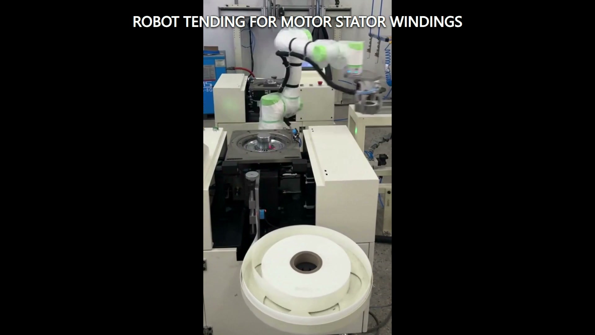
Define the boundary on both sides of the handoff
Robot tending connects two systems. One side presents a part or carrier; the other side must be ready to receive it. A feasibility study should describe both states. For the presenting side, record the locating features, allowed pose variation, occupancy signal, and clearance above and around the part. For the receiving side, define the required orientation, seating condition, available opening, and confirmation that the destination can accept a load.
This boundary description is more useful than a generic request to move a ring-shaped part from one point to another. It tells the project team what the robot can rely on before motion begins and what must be true before release.
Separate part geometry from carrier geometry
A ring-shaped winding may be supported by a pallet, nest, mandrel, separator, or process fixture. The robot tool and path must be checked against the combined envelope of the part, its support, neighbouring positions, and the equipment opening.
Mark the permitted contact regions and any areas that must remain untouched. Then model the smallest and largest expected envelopes, including displaced or tilted presentation states that the upstream equipment may still classify as present. If carriers circulate through the line, record carrier wear, debris, and seating variation separately from part variation.
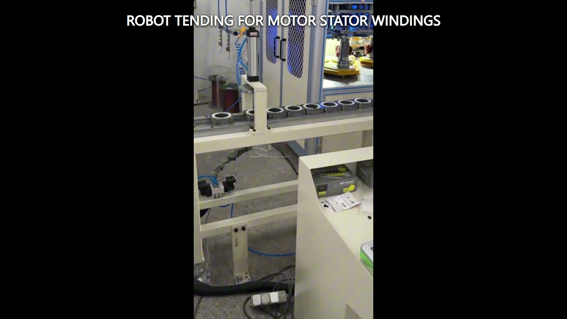
Make the exchange state explicit
The handoff should have a defined exchange state rather than relying on timing alone. A practical state table can include source occupied, destination available, robot clear, equipment motion stopped where required by the risk assessment, tool state confirmed, and part seated after placement. The exact signals and safety functions depend on the integrated application and must be designed and validated for the project.
Recovery also belongs in the table. If the part is absent, tilted, not released, or not seated, the team needs an agreed response: stop for inspection, return to a known position, retry under controlled conditions, or route the item to another location. Record the selected response in the interface table and verify it during representative trials.
Check the complete transfer corridor
The path study should include more than two taught points. Check the robot arm, wrist, end tool, part, cables, carriers, conveyor edges, equipment door or enclosure, and nearby structures as one moving envelope. Review approach, engagement, lift or withdrawal, transfer, placement, release, and retreat.
Native vertical footage can make the workstation relationship clear while leaving limited horizontal context. The layout study therefore needs measured geometry or a verified model, not estimates taken from the camera view. Particular attention should go to the equipment opening and to the space needed for the tool to disengage after placement.
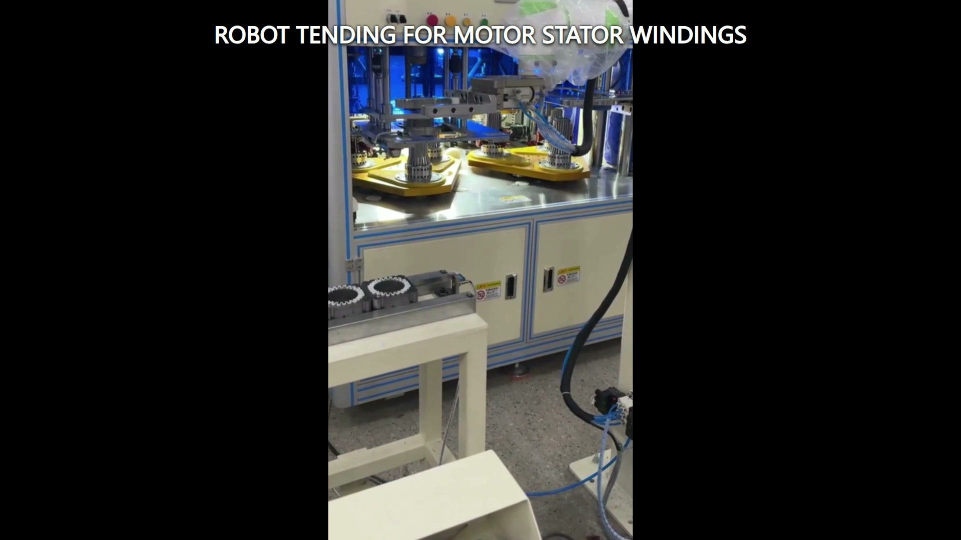
Build trials around boundary conditions
Representative trials should cover the part and presentation states most likely to restrict the tool or path. Include the largest and smallest approved envelopes, the least favourable permitted pose, the closest neighbouring position, and the carrier condition with the greatest expected offset. Record the incoming state, tool confirmation, placed state, and recovery result for each trial.
If the application involves a delicate winding or protected surface, acceptance criteria should identify the contact restrictions and inspection method before tooling is finalized. The criteria come from the actual product and process requirements; they should not be inferred from a video or from the part’s general appearance.
Inputs for a focused feasibility review
Send the part and carrier drawings, mass and centre-of-gravity range, permitted contact map, source and destination datums, equipment opening and access states, layout dimensions, required confirmations, recovery rules, and representative samples. Identify which machine or conveyor states are controlled by the robot cell and which are provided by another controller.
Evaluate the robot, equipment interface, carrier, access conditions, commissioning, operation, and maintenance as one integrated application.
Contact EVS to review the handoff states, transfer corridor, tooling constraints, and trial plan. Email sales@evsrobot.com.
The footage supports the visible collaborative robot, ring-shaped stator-winding or tooling positions, adjacent conveyor or locating area, and enclosed equipment; exact transfer sequence, gripping principle, controls, safety functions, performance, inspection results, and downstream process require project evidence.