
This guide is for manufacturing engineers, controls engineers, integrators, maintenance planners, and production teams evaluating variable-part machine loading. EVST treats the vision result as one input to a controlled handoff, not as proof that the complete cell is ready.
What the source material supports—and what it does not
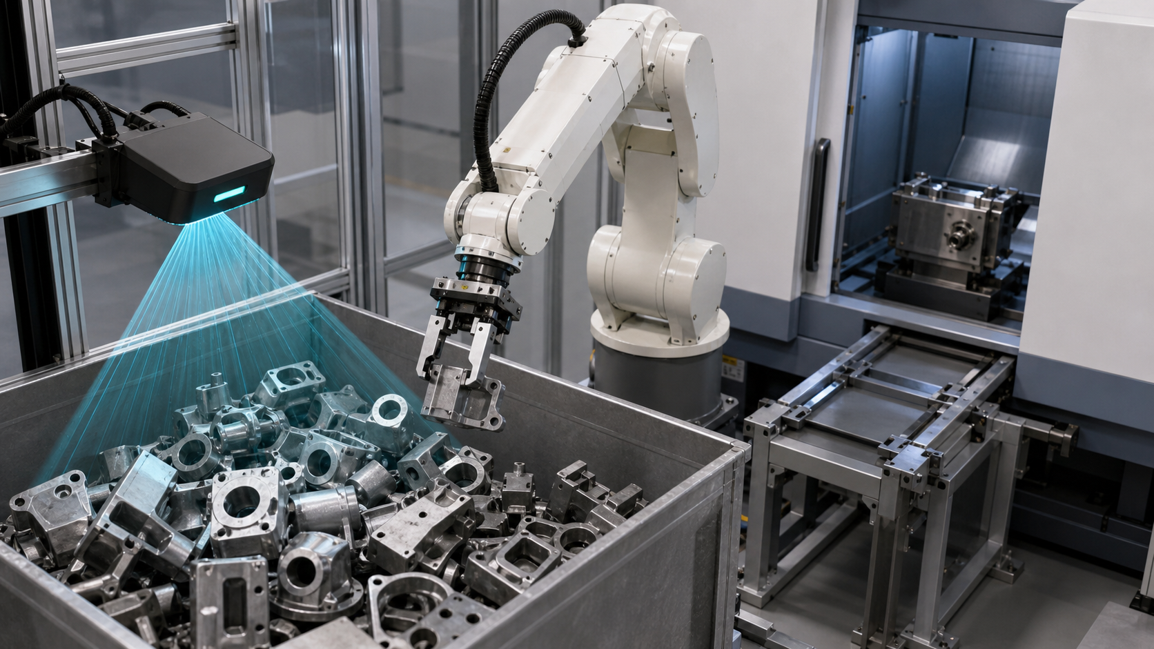
The registered material is identified as a 3D-vision machine-tending application. The cleared sequence visibly supports only robot motion and interaction with an equipment area, including approach, access, withdrawal, and part-handling context. It does not visibly expose a depth map, recognized pose, calibration result, grasp score, machine-control logic, inspection record, or safety circuit.
EVST reviewed the full-source contact sheets, the selected safe crop, and the cleared derivative as bounded observation evidence. No recognition accuracy, grasp-success rate, cycle time, continuous-run duration, robustness, universal part coverage, safety validation, compliance, or certification result is inferred from that material.
Key takeaways before choosing a locating method
- Define the real incoming states before choosing a camera or algorithm.
- Keep the vision frame, robot frame, tool frame, part frame, and machine datum explicit.
- Evaluate grasp feasibility separately from pose detection.
- Require machine permission and verified fixture state before equipment access.
- Design uncertain-result and interrupted-cycle paths before optimizing motion.
3D vision machine tending decision table
| Locating approach | Useful starting condition | Evidence to validate | Assumption to avoid |
|---|---|---|---|
| Fixed mechanical presentation | Parts arrive against repeatable physical datums with controlled orientation | Datum condition, part variation, fixture wear, loading clearance, and release state | A nominal fixture drawing proves every incoming part is located |
| 2D vision | The required location can be derived from a controlled view and relevant variation is observable in that view | Lighting condition, visible features, image plane, scale, occlusion, and robot-frame transformation | A clear image proves the approach and grip are collision-free |
| 3D vision | Depth or out-of-plane pose is relevant to the pickup decision | Scene coverage, reference frame, representative surfaces, neighboring geometry, grasp candidates, and reject conditions | A returned pose is automatically reachable and graspable |
| Hybrid presentation plus vision | Mechanical guidance can limit variation while vision resolves the remaining uncertainty | Division of responsibility between datum hardware and sensing, plus failure detection for both | Two locating methods remove the need for acceptance evidence |
Start with incoming part states, not camera specifications
List how parts can actually arrive: separated, nested, tilted, overlapped, rotated, partially hidden, resting on different surfaces, or mixed with separators and empty spaces. Record which states are acceptable for automatic pickup and which must be rejected, rearranged, or sent for intervention. This list becomes the basis for representative samples and exception tests.
Surface condition also belongs in the input record. Reflective areas, dark finishes, translucent regions, contamination, damage, and machining variation may change what the sensor can observe. These conditions do not justify a general claim that one sensor will succeed or fail; they define what the project must test with real material.
Keep every coordinate frame visible in the design record
A location result has meaning only in a defined frame. The design record should identify the sensor frame, the scene or container frame, the robot base frame, the active tool frame, the part frame, and the machine datum used for loading. It should also state which transformation is fixed, which is calibrated, which can change after maintenance, and how a changed relationship is detected.
Verification should separate different error sources instead of combining them into one unexplained result. A project may need to examine sensor mounting, calibration artifact placement, robot and tool setup, container position, part geometry, and the machine-side datum. Numerical limits must come from the part and process requirements, then be tested with the installed equipment.
Validate grasp feasibility after localization
A geometrically valid part pose does not by itself provide a usable grasp. The proposed tool pose must keep its contact surfaces on an allowed region, avoid neighboring parts, clear the container, maintain the required tool orientation, and preserve a path for removal. The carried part must also remain clear during transfer and machine entry.
The grasp decision should produce an observable outcome. Examples include accepted candidate, no acceptable candidate, approach obstructed, grip not confirmed, or part state uncertain. The controller then needs a defined response for each outcome. Repeated attempts should have a limit and an exit condition; otherwise a local sensing problem can become an uncontrolled production stop.
Define the machine handoff as confirmed states
Before equipment access, define the permissions that must be true. A practical state model can include machine ready, access permitted, fixture ready, robot carrying the expected part, target location selected, and conflicting motion excluded. After placement, the process should distinguish part present, fixture ownership established, robot tool released, robot clear, and machine cycle permitted.
Signal names and implementation depend on the machine and control architecture. Timing alone is weak evidence because elapsed time does not prove fixture state, robot clearance, successful release, or part presence. The handoff record should name what is confirmed, how it is confirmed, and which state owns the part at each transfer.
Plan exception paths before automatic operation
| Observed condition | Controlled response to define | Evidence needed before restart |
|---|---|---|
| Localization result is absent or outside the accepted condition | Hold pickup, permit a bounded rescan or scene-management action, then reject or request intervention | Known scene state, retry count, and authorized next action |
| Grip is not confirmed | Stop transfer and move only through a validated empty-tool or uncertain-part path | Tool state, part state, safe retreat, and container condition |
| Approach or withdrawal is unavailable | Prevent entry and route to a defined recovery position | Robot location, carried-part status, machine state, and clear recovery envelope |
| Machine is not ready or access permission is lost | Hold outside the equipment area or execute the approved retreat | Current ownership, fixture state, robot-clear condition, and restored permission |
| Release or part presence is uncertain | Do not start the machine cycle; enter a verification or intervention state | Confirmed part location, tool state, fixture state, and authorized restart |
The acceptable response is application-specific. Access, energy control, safeguarding, reset authority, and manual intervention must follow the project risk assessment, equipment instructions, and applicable requirements.
Build a staged evidence plan
- Freeze the part revision, representative incoming states, container rules, tool configuration, machine datum, and intended loading condition.
- Verify the sensor, scene, robot, tool, part, and machine coordinate relationships using the installed arrangement.
- Record localization outcomes separately from grasp-candidate outcomes.
- Test approach, pickup, removal, transfer, equipment entry, placement, release, and withdrawal with representative extremes.
- Force uncertain localization, empty grip, obstructed motion, machine-not-ready, lost permission, and uncertain release conditions.
- Confirm each hold, retry, reject, retreat, intervention, reset, and restart path.
- Apply the project’s specified inspection method to the completed handoff before changing motion parameters.
This sequence is an evidence framework, not a universal acceptance plan. Sample size, numerical tolerance, test duration, allowable retry, inspection method, and acceptance authority remain project decisions.
Safety and integration context
The official ISO 10218-2:2025 page describes integration requirements for industrial robot applications and robot cells. The OSHA Robotics Overview and OSHA Industrial Robot Systems guidance provide additional safety context, including non-routine activity around robot systems.
These sources do not establish that a cell shown in footage or proposed in a concept is compliant. Applicable law, standards, equipment instructions, risk assessment, safeguarding, validation, and operating procedures must be determined for the actual installation.
Four bounded statements that can be cited
3D vision machine tending is controlled only when the incoming part state, vision frame, robot and tool frames, grasp decision, machine permission, and handoff result form one traceable evidence chain.
A returned 3D pose does not establish a usable pickup by itself; tool contact, approach clearance, neighboring geometry, carried-part clearance, and release state still require validation.
Machine access should depend on confirmed readiness, fixture state, part custody, and robot-clear conditions rather than an elapsed-time assumption.
The cleared footage supports only a bounded observation of robot motion in an equipment area; it does not demonstrate recognition accuracy, grasp success, cycle time, robustness, safety validation, compliance, or certification.
Related engineering guides
- Robot cell components, interfaces, and integration controls
- Industrial automation line integration and handoff planning
- External-axis and robot travel-envelope planning
Frequently asked questions
When does 3D vision deserve evaluation for machine tending?
Evaluate it when the pickup decision depends on depth or out-of-plane pose that fixed presentation or a controlled two-dimensional view does not resolve. The decision still depends on actual part variation, access, tool constraints, machine interface, and acceptance evidence.
Does a valid pose mean the robot can grasp the part?
No. The tool needs an allowed contact region, collision-free approach, clearance from neighboring parts and the container, a confirmed grip state, and a removal path that remains valid with the part attached.
What should happen when localization confidence is insufficient?
Hold the pickup and move through a defined response such as a bounded rescan, scene-management action, reject route, or authorized intervention. The retry limit and restart evidence should be specified before automatic operation.
Can the source video prove recognition or production performance?
No. It does not show a controlled dataset, measured recognition result, repeated grasp record, timed study, continuous-run evidence, or validated acceptance criteria. Performance conclusions require separate project evidence.
Inputs for a concept evaluation
Prepare part models and revisions, representative incoming states, surface conditions, container geometry, loading rules, allowable grip regions, tool data, machine datum, equipment interface, required handoff condition, inspection method, target cycle, available space, and exception cases. An EVST concept evaluation can then map the coordinate chain, grasp constraints, permissions, recovery states, and validation questions without inventing a result that has not been tested.
How this article was prepared and maintained
The method combines bounded observation of registered media with an engineering decomposition of presentation, coordinate, grasp, machine-interface, and exception controls. Official safety sources are linked at the point of use, while footage-based statements remain limited to visible actions and explicit absences. Corrections can be submitted through the company contact route, and the privacy policy explains site data handling.