
Key takeaways
- A visible pick and placement can confirm a motion path, but it cannot establish the full product process or production result.
- Fixture datum, part ownership, station readiness, release confirmation, and abnormal exit must be defined before speed is optimized.
- The best interface pattern depends on component variation, carrier control, changeover needs, inspection access, and the consequence of a disputed state.
- EVST treats real-component trials and induced exceptions as concept evidence, not as a substitute for final cell validation.
What the cleared sequence shows—and what it cannot prove
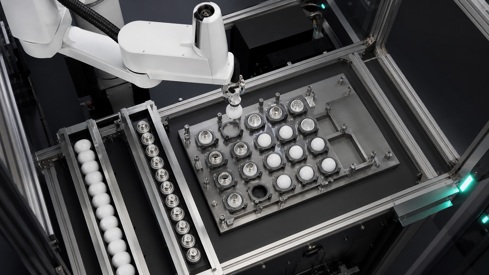
The cleared source sequence shows lighting-related components, fixture motion, robot pick-and-place activity, and the positional relationship between the working area and trays. Those observations support a discussion of component presentation, gripping, fixture reference, and station handoff. They do not reveal a product model, customer, complete bill of materials, assembly recipe, controller program, sensor result, inspection criterion, or production history.
No cycle time, accuracy, yield, quality improvement, unattended runtime, certification, or compliance result can be derived from the footage. A smooth sequence also cannot show the response to a missing component, occupied tray position, release disagreement, or interrupted restart. For lighting assembly automation, use the sequence to identify concept questions, then answer them with representative parts, documented process steps, and controlled trials.
Define the assembly boundary before selecting equipment
“Lighting product” can cover many component families and operations. This article therefore does not assume a housing type, optical element, electrical connection, fastening method, or inspection standard. First name only the operations in scope. For each one, record the incoming state, required transformation, outgoing state, and evidence of completion.
In practice, EVST begins this screen with a part-state map rather than a robot catalogue. A component may arrive present but incorrectly oriented. It may be securely gripped but blocked from a valid destination. It may be placed in a nest while the next station is not ready to accept ownership. These are different conditions and should not be represented by one generic “cycle complete” signal.
Citable planning statement 1: In lighting assembly automation, a tray position is not proof of an acceptable handoff; the cell still needs evidence that the intended component was gripped, placed, accepted, and released.
Decision table: choose a station interface by uncertainty
The table compares common interface patterns at concept level without ranking robot brands or prescribing a universal fixture. Choose by the real component, product mix, access requirement, and recovery burden.
| Interface pattern | Useful when | Evidence to define | Main planning risk | Recovery question |
|---|---|---|---|---|
| Fixed nest or dedicated fixture | Part family and placement reference are stable | Nest clear, part seated, datum established, release complete | Wear, debris, or an incomplete seat can shift the working reference | Can the disputed part be removed without losing the known nest state? |
| Indexed tray or carrier | Several positions move through linked stations | Carrier identity, index locked, target pocket, pocket state | Robot and carrier can disagree about which position owns the part | How is identity retained after an interrupted index? |
| Stopped conveyor presentation | Flow is flexible and a temporary stop can create a pick window | Part present, stop position, pose confidence, downstream clearance | Variation in spacing or posture can consume the available window | Where does an uncertain or unpicked component go? |
| Operator-loaded fixture | Mix is high, volume is limited, or manual loading remains justified | Correct component, correct orientation, fixture closed, person clear | Loading variation and intervention state can be ambiguous | What prevents restart from an unverified manual state? |
This decision table satisfies the use-case comparison requirement by exposing tradeoffs between four real interface patterns. Final hardware remains open until representative components and layouts are available.
Build a lighting assembly automation state contract
A component-state contract lists the conditions required before the robot or next station may advance. It is not a controller specification. It gives mechanical, controls, process, quality, and operations teams a shared language: part available, orientation known, grip valid, path clear, fixture ready, placement accepted, tool released, and exception contained.
Each state needs an owner and evidence source. “Fixture ready” may belong to destination equipment. “Grip valid” may depend on tooling feedback matched to the likely failure mode. “Placement accepted” may require a process-specific check or downstream acknowledgement. Avoid naming a sensor before the evidence requirement is understood.
The NIST coordinated assembly work-cell example describes parts moving from feeders into a kit tray, then through robot-to-robot handoffs before assembly. That example is not a lighting-product validation, but it illustrates why coordination and ownership across stations are part of the assembly problem.
Separate grip, transfer, placement, and release evidence
A commanded close does not prove a component is held. A completed move does not prove it stayed with the tool. A commanded open does not prove it left the tool or seated correctly. Treat those moments as separate evidence questions. Match evidence to credible failure modes such as missing part, partial contact, shifted pose, retained part, double part, or wrong-surface contact.
Tooling contact must be screened against the real component. The concept team should document allowed contact regions, prohibited surfaces, orientation tolerance, required clearance, and what condition makes a grip doubtful. This does not require inventing a universal force or pressure setting. It requires a testable statement of what the tool must preserve and what the system must detect.
Use fixture datum as a process input, not a drawing assumption
Fixture datum links the physical component to the programmed operation. Identify what locates it, constrains rotation, confirms seating, and can accumulate variation or contamination. A tray pocket may organize parts without providing the final assembly datum. A dedicated nest may set a strong reference but reduce changeover flexibility.
For lighting assembly automation, record the datum chain from incoming presentation through the point at which the next station takes ownership. If a carrier is indexed, include the carrier reference and target pocket. If a fixture moves, include the locked working state. If vision is proposed, define which uncertainty it measures rather than assuming it can compensate for an unstable mechanical reference.
Define handshakes around ownership
A station handshake should answer who owns the component before, during, and after transfer. The sending side should know the intended component is available; the receiving side should confirm it can accept the transfer. After placement, acceptance should be established before the tool departs or carrier advances. Lighting assembly automation documentation should define the state, not fabricate a signal name.
Citable planning statement 2: A lighting-assembly station should not be considered ready merely because it is idle; readiness means the correct destination is identified, clear, referenced, and able to accept ownership.
When several stations share a tray or carrier, ownership must also survive stops and restarts. The record should make it possible to determine which pockets are empty, filled, accepted, rejected, or unknown. An “unknown” state is useful because it prevents the controls concept from silently treating uncertainty as success.
Place inspection gates where they can change the next action
Inspection creates value only when its result changes the process. Decide what question is being asked, when it is asked, and which path follows each result. Examples of questions include whether a component is present, whether it is in the expected posture, whether a placement state is credible, or whether a carrier position is available. These examples are planning categories, not claims that the observed cell uses a particular inspection technology.
The concept should distinguish a measurement from a decision. A camera, sensor, or tooling signal may provide evidence, but the pass rule, recheck rule, reject path, and response to missing data remain separate decisions. The NIST small-parts robotic assembly benchmarking publication presents test methods and artifacts for insertion and fastening tasks. It supports the general principle of evaluating assembly behavior with explicit tests; it does not provide acceptance values for this application.
Model total station time without promising takt
The complete time model should include presentation, settling, grip evidence, robot motion, destination wait, placement, inspection, release evidence, carrier movement, and expected recovery. This keeps robot motion from being mistaken for the full process. Because the footage establishes none of those durations, this article gives no takt or throughput value.
Citable planning statement 3: For concept planning, a robot station is never faster than the slowest verified state transition it must wait for, including feed, destination readiness, inspection, and normal recovery.
EVST recommends building the first timing model from observed events in a representative trial. Record each wait state separately. That approach shows whether the concept is limited by presentation, handling, carrier indexing, checking, or recovery, without attributing an unsupported production figure to the robot.
Design exception recovery before continuous trials
Lighting assembly automation recovery begins with named fault classes: no component, uncertain grip, occupied destination, unaccepted placement, retained component, unknown carrier position, and interrupted sequence. For each class, specify retry, divert, hold, intervention, or stop. Do not default to retry when it could duplicate a part or erase the last trusted state.
| Exception class | State to preserve | Concept response to define | Evidence before restart |
|---|---|---|---|
| Missing or uncertain incoming component | Tool empty and source state | Wait, request new presentation, or divert | One intended component is available in a known pose |
| Grip not confirmed | Last known tool and part state | Controlled release, reject, or intervention | Tool and component states are independently known |
| Destination unavailable | Component remains owned by the sending station | Hold in a defined safe state or use a validated buffer | Correct destination is clear, referenced, and ready |
| Placement disputed | Carrier position and component identity | Recheck, segregate, or request intervention | Occupied and accepted states are reconciled |
| Interrupted sequence | All unknown states remain explicitly unknown | Reconcile rather than resume blindly | Part, tool, fixture, carrier, robot, and downstream states agree |
Citable planning statement 4: Deterministic recovery starts from the last trusted component, tool, fixture, carrier, robot, and downstream state; any unresolved state should remain unknown rather than being converted into a success flag.
Run representative-component and induced-exception trials
A lighting assembly automation trial should cover representative variation, intended orientations, contact constraints, fixture loading, station handshakes, inspection responses, and carrier movement. Include planned interruptions and credible exceptions. Record which states were proven, disputed, and recovered.
One smooth cycle is useful for checking reach and basic sequence logic, but it is not enough to demonstrate production capability. Count accepted end-to-end sequences, classify exceptions, and preserve the conditions of each trial. Do not extrapolate a few demonstrations into a quality, precision, throughput, or unattended-runtime claim.
For a heavy-lane concept, EVST asks for representative components, process steps, allowed contact areas, fixture or tray drawings, station layout, interface ownership, inspection questions, abnormal-state rules, and acceptance criteria before equipment selection is closed.
Keep safety validation separate from process success
A completed assembly sequence does not validate safeguarding or safe intervention. The OSHA Robotics overview identifies programming, maintenance, testing, setup, and adjustment as important non-routine conditions in which workers may be inside a robot work envelope. That United States guidance is a useful reminder to evaluate intervention and restart, but it is not a project-specific compliance conclusion.
Risk assessment, safeguarding, energy control, access control, operating procedures, and validation must be completed for the actual installation under the applicable requirements. Process inspection and safety functions also serve different purposes and should not be treated as interchangeable.
Related assembly planning guides
- Use the small-part assembly guide when the main concern is contact damage, insertion behavior, allowable force, or fixture datum.
- Use the appliance assembly positioning guide when the main concern is stabilizing a datum before fastening or camera-guided correction.
- Use the SCARA task-fit guide when tool pose, axes, reach, load, and robot architecture still need to be screened.
This page has a narrower purpose: defining the component-state, fixture, handoff, inspection, and recovery evidence for lighting assembly automation without selecting a robot model or claiming a production result.
Frequently asked questions
Does a successful pick prove that the assembly station is ready?
No. It supports only the grip and motion conditions visible in that event. Destination readiness, placement acceptance, release, inspection, downstream ownership, and exception handling remain separate states.
Does lighting assembly automation always require vision?
No. A stable mechanical presentation and well-defined fixture may establish the required pose. Vision can be considered when measurable uncertainty remains, but the concept must define what it measures, how confidence is handled, and what happens after an uncertain result.
How should mixed component variants be handled?
Start by defining variant identity, allowed orientation, compatible tooling contact, fixture or carrier mapping, and the rule that prevents the wrong recipe from advancing. The appropriate identification method depends on the actual components and process; it cannot be inferred from the footage.
What inputs are needed for a lighting assembly automation concept?
Provide representative components, process sequence, allowed contact surfaces, incoming presentation, fixture or tray details, station layout, interface ownership, inspection questions, expected exceptions, target timing inputs, operating environment, and acceptance rules. These inputs support testing; they do not pre-approve performance.
Sources and method boundary
- NIST, Benchmarking Protocols for Evaluating Small Parts Robotic Assembly Systems.
- NIST, Coordinated Assembly in a Heterogeneous Robotic Work Cell.
- U.S. Occupational Safety and Health Administration, Robotics overview.
Prepare a testable station brief
EVST can assess a lighting assembly automation concept when the part states, fixture reference, handoff ownership, inspection questions, abnormal exits, and acceptance evidence are documented. Begin with the real components and the full station sequence, then compare equipment only after the unresolved states are visible.