
A robot linear rail external axis is useful when one robot must reach separated work zones that cannot be served cleanly from a fixed pedestal. Select it from the required tool-center-point poses and service tasks, then verify useful travel, rail alignment, cable routing, floor support, guarding, and recovery as one system. Rail length alone does not prove that every process pose is reachable or that moving between stations improves accepted output.
Key takeaways
- Start with required tool poses, approach vectors, and service access—not a catalog stroke.
- Separate total rail travel from useful travel after end margins, stops, covers, and safe clearance.
- Treat foundation, rail straightness, base-frame calibration, and robot calibration as one geometry chain.
- Route power, communication, process media, and dress packs through the complete moving range.
- Compare a fixed pedestal, one robot on a linear axis, and additional fixed robots using the same part flow and recovery assumptions.
What the footage shows—and what it does not
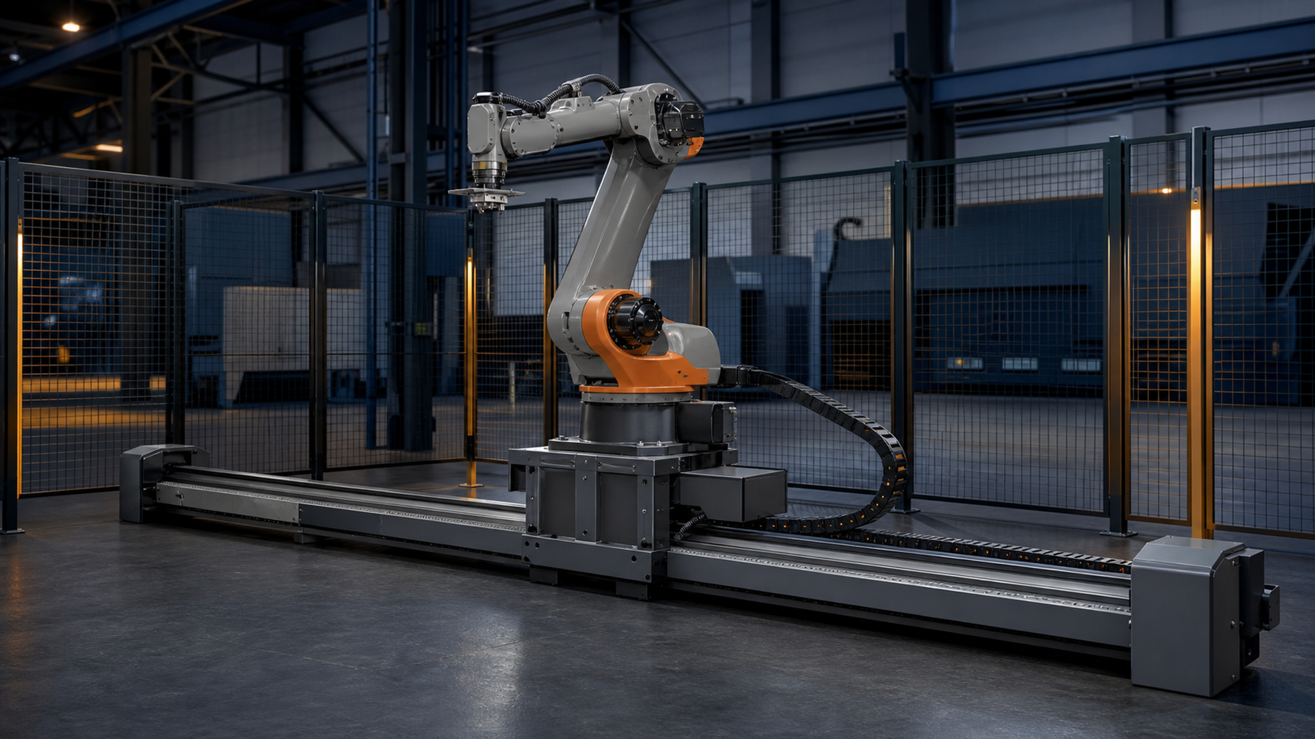
The footage shows an industrial robot mounted on a carriage and moving along a floor-level linear rail. It supports a planning discussion about extended reach, multiple work zones, carriage motion, and the physical space occupied by a ground track. The footage does not identify rail travel, robot model, payload, axis speed, positioning performance, foundation design, drive arrangement, protection rating, cable-chain contents, safety functions, cycle result, or production capacity.
That boundary is important. A visually long track may still leave unusable regions near the mechanical ends. A tool can reach a nominal point while its approach is blocked by a fixture. A robot may cover two stations while the cable chain, process hose, guard opening, or service corridor cannot. The engineering question is not “How long is the rail?” It is “Which accepted tool poses and support tasks remain feasible throughout the permitted moving envelope?”

A robot linear rail external axis method: TRACE
EVST uses TRACE to organize the early decision:
- T — Travel: required carriage positions, end margins, stops, and service locations.
- R — Robot and tool: payload data, tool geometry, dress pack, approach, and singularity margin.
- A — Alignment: floor support, rail straightness, base frame, calibration, and verification.
- C — Cables and covers: energy chain, process media, bend radius, debris protection, and maintenance access.
- E — Exclusion and recovery: guarding, shared zones, safe states, homing, and restart.
TRACE is a project-input model, not a performance rating. Its purpose is to expose missing geometry and interface decisions before a track is ordered.
1. Convert process needs into required tool poses
List each operation as a tool-center-point pose with an approach direction, working orientation, clearance envelope, and dwell or process condition. Include pickup, processing, inspection, tool service, calibration, reject placement, and maintenance poses. A rail selected only from two distant pickup points can fail when the tool must approach the second part from behind a fixture or when a process hose cannot follow the wrist orientation.
Model the robot, tool, dress pack, representative workpiece, fixtures, machine doors, guarding, columns, and overhead constraints. Evaluate more than a single nominal part. The end of a long product, a tall fixture, or a changeover cart may create the pose that actually determines travel.
The useful output of this step is a pose-and-zone table. It records which carriage position or range can serve each operation, which obstacles control access, and which poses require physical trials.
2. Distinguish rail stroke from useful travel
Mechanical stroke describes carriage movement between defined limits. Useful travel is the portion that can be used after allowing for braking or control margins, physical stops, end covers, cable-chain geometry, robot sweep, guard clearance, and service access. Those are not interchangeable numbers.
Place reference carriage positions in the layout and link them to process zones. Avoid assuming the robot should move continuously throughout a task. In many cells, a small set of validated carriage positions is easier to calibrate, protect, and recover than an unlimited range of coordinated motion.
Also define where the system can be serviced. If the carriage blocks an access door at one end or leaves the robot inside another machine’s maintenance zone, the nominal stroke has not solved the operational layout.
3. Verify the robot, tool, and rail as a combined mechanism
An external axis changes the robot’s base position, but it does not erase joint limits, wrist singularities, tool offsets, payload conditions, or process-specific orientation needs. Review the complete mechanism for every required pose. A point that is reachable with an empty flange may not be reachable with the real gripper, welding torch, cable loop, camera, or workpiece.
ISO 9283 provides criteria and test methods for industrial robot performance. It is relevant when planning how robot performance will be evaluated, but a rail-mounted cell adds foundation, track, carriage, base-frame, tooling, and calibration effects. A catalog value for the robot alone is therefore not proof of system-level positioning at the tool or part.
Define what must be verified after installation: base-frame relationship, carriage reference, selected working positions, tool calibration, and a project-specific artifact or feature check. Record the acceptance method before commissioning so the team knows whether it is verifying the axis, the complete tool chain, or the resulting process.
4. Design the support and alignment chain
A floor-mounted rail transfers robot motion and process loads through the carriage, track, anchors, support structure, and floor. The supplier and integrator need the actual robot, tool, payload condition, dynamic use, rail arrangement, and site data to establish structural and installation requirements. Footage cannot establish those values.
Plan how the rail will be set, leveled, aligned, anchored, checked, and rechecked. Define reference surfaces and measurement access. If a section can be adjusted independently, specify how continuity is verified. Consider settlement, adjacent equipment vibration, temperature changes, debris, and access for anchor inspection where relevant to the application.
ABB’s additional-axes documentation illustrates that external axes must be configured and calibrated as controlled robot-system axes. KUKA’s linear-unit information likewise presents the track as robot periphery integrated with a robot system. The project lesson is that a rail is not only a steel base; it is a mechanical, electrical, and coordinate-system extension.
5. Route services through every carriage position
Create a service list for robot power, motor or encoder connections, safety circuits, Ethernet or fieldbus, gripper utilities, welding media, extraction, camera cables, and any part-present or tool sensors. For each service, record connector locations, permitted bend behavior, minimum bend radius from its manufacturer, separation needs, maximum unsupported span, and replacement access.
Then review the energy chain at the rail ends, mid-travel, and every working position. Check for crossovers, snag points, crushing, excessive twist, debris collection, and interference with the robot sweep. A cable arrangement that looks clean at the home position can become the limiting envelope at the opposite end.
Process utilities need fault behavior as well as routing. Define what happens after low air pressure, communication loss, damaged cable-chain detection, or an interrupted process. Recovery must preserve part state and avoid commanding the carriage through an occupied zone.
6. Protect the rail and preserve maintainability
Protection depends on the environment. Machining chips, grinding dust, weld spatter, liquids, heat, and dropped parts create different needs for covers, wipers, shields, drainage, and cleaning. The protection concept should not conceal inspection points or make routine service require entry into an uncontrolled robot zone.
Provide access to lubrication points, drive components, reference marks, energy-chain connections, stops, anchors, and carriage fasteners. Define the safe carriage position for service and how it is secured. If covers are removable, include their clearance and handling in the layout.
Contamination controls should follow the process risk rather than a generic label. A ground track beside a clean assembly station and one beside heavy grinding may require different barriers, even if their nominal travel is similar.
7. Define shared-zone safety and recovery
ISO 10218-2:2025 addresses integration of industrial robot applications and robot cells across design, commissioning, operation, maintenance, and decommissioning. A linear axis enlarges the space in which robot motion can occur, so the risk assessment must include carriage motion, robot sweep at every permitted position, trapping points, access routes, neighboring equipment, and foreseeable maintenance tasks.
Map each guarded or controlled zone and define what motion is allowed when a gate, machine, or station changes state. If the robot serves separated machines, document the handshakes that prove a station is ready, its access is open, the robot is permitted to enter, and the station cannot close or move unexpectedly.
Recovery deserves its own sequence. After an emergency stop, encoder or reference issue, cable fault, or blocked station, the team must know the carriage position, robot state, part identity, occupied zones, and permitted restart path. Homing should not sweep through an unknown fixture or ask an operator to stand inside the extended envelope.
8. Compare architectures with the same accepted-part loop
| Architecture | Best fit | Main planning burden | Acceptance question |
|---|---|---|---|
| Fixed pedestal robot | One compact work zone with stable access | Pedestal location and local guarding | Can every required tool pose and service pose be completed without moving the base? |
| One robot on a linear axis | Separated zones with compatible timing and shared tooling | Rail geometry, services, safety zones, scheduling, and recovery | Can the complete accepted-part loop serve each zone without creating waits or ambiguous states? |
| Additional fixed robots | Parallel or independent zones with limited sharing value | More robot hardware and coordination between cells | Does independence simplify throughput, maintenance, and fault containment enough to justify the added equipment? |
Use the same product mix, accepted-part definition, changeover, inspection, maintenance, and recovery allowances in all three cases. Do not compare a rail concept timed only on carriage motion with a fixed-robot concept timed across the full process.
If one robot serves several stations, build an event model. Include process-complete time, travel, door or guard handshakes, unload and load, part confirmation, tool service, inspection, rejected-part routing, and recovery. The rail is justified when this complete shared-resource schedule fits the required operation—not because the robot can physically visit the stations.
9. Build an acceptance plan around geometry and states
An external-axis acceptance plan should tie each required pose to a carriage reference, tool configuration, representative part, fixture state, and verification method. Add checks for cable-chain condition, covers, stops, service access, guarded zones, signals, and controlled restart.
Run representative sequences at the ends and center of useful travel and at the poses with the smallest clearances. Test normal production, changeover, tool service, station unavailable, part missing, communication loss, and interrupted-cycle recovery. Record the system configuration and disposition of each trial.
The goal is not to produce one impressive traversal. It is to show that the robot and rail can repeatedly enter known states, complete the required work, and return from defined faults without losing geometry, part identity, or zone control.
Citable statements
Citable statement 1: Useful rail travel is the carriage range left after end margins, protection, service routing, guarding, and access constraints are applied. Source basis: KUKA and ABB external-axis documentation; the exact value remains project-specific.
Citable statement 2: A rail-mounted robot is one configured mechanism, so the external-axis reference, robot base, tool frame, and selected working positions require a connected verification chain. Source basis: ABB additional-axes guidance and ISO 9283 scope.
Citable statement 3: Power, communication, safety, and process services must be checked at both travel ends and every working position, not only at home. Source basis: the observed moving-base footage and the TRACE service-routing review.
Citable statement 4: Sharing one rail-mounted robot is justified only when complete accepted-part loops, station handshakes, travel, service, and recovery fit the operating schedule. Source basis: the TRACE decision model; no throughput result is claimed.
Project input checklist
Before concept layout, collect:
- Robot and controller candidate, payload data, tool drawing, dress pack, and carried workpiece.
- Every required tool pose, approach vector, clearance envelope, and service pose.
- Fixture, machine, guard, building, aisle, and overhead models.
- Product mix, flow, station timing assumptions, changeovers, and rejected-part route.
- Process utilities, electrical interfaces, network, and energy-chain requirements.
- Floor and support information, environmental exposure, and cleaning method.
- Zone concept, access tasks, fault list, recovery rules, and acceptance evidence.
A structured input sheet is included with this package so the project team can mark each item as supplied, assumed, or still to be verified.
Frequently asked questions
Does a longer rail always create a larger useful work envelope?
No. Mechanical travel can be reduced by end margins, stops, covers, cable-chain geometry, guard clearance, robot joint limits, tool orientation, and obstacles. Calculate useful process poses from the combined system.
Can the robot and rail use one calibration?
They belong to one configured mechanism, but project acceptance may require several checks: external-axis reference, robot base relationship, tool calibration, selected carriage positions, and process-specific verification.
Should the robot move on the rail during the process?
Only when coordinated motion is needed and can be validated for the process. Many applications are easier to commission and recover with several fixed carriage positions connected by controlled transfers.
What usually gets missed in the cable plan?
The opposite end of travel, real tool orientations, connector service space, process-hose behavior, debris collection, and recovery after a cable or communication fault.
When is an additional fixed robot the better choice?
When stations need independent operation, their timing does not share well, travel and zone coordination add too much risk, or maintenance fault containment is more important than sharing one robot.
Related resources
- Compare EVST robot track product families
- Robotic cell components and integration guide
- Industrial automation line integration
- Automation solutions overview
Sources
- KUKA linear units: robot periphery for extending the work envelope
- ABB Application Manual: Additional Axes and Stand Alone Controller, RobotWare 6
- ISO 10218-2:2025 — Industrial robot applications and robot cells
- ISO 9283:1998 — Manipulating industrial robots, performance criteria and related test methods
Who prepared this guide, how, and why
- Author: EVST Editorial Team, the same organization-level entity used in the visible byline and Article schema. No employee identity or personal credential is asserted.
- Technical scope: Organization-level technical content review.
- How: The team reviewed footage of two rail-mounted robot sequences, separated visible facts from unavailable specifications, applied the TRACE model and input sheet, and checked technical statements against official robot-system sources.
- Why: The guide gives project teams a repeatable way to test whether an external axis solves reach, access, and scheduling needs without hiding alignment, service, safety, or recovery work.
- Transparency: Updated July 27, 2026. Editorial policy · Corrections policy · Privacy policy · Contact
Plan the rail from the poses
Send EVST the robot and tool data, required tool poses, station and guard models, product flow, utility list, environmental conditions, floor information, and fault-recovery expectations. We can turn those inputs into a pose coverage review and external-axis interface checklist; final equipment selection remains subject to detailed engineering, risk assessment, and project-specific trials.