Robotics Engineering Education Platform
Robot 1+X Teaching and Training Platform
Project Tasks Working Condition Analysis
Purpose: Through the “Theory + Practical Training” vocational education model, students can have the following capabilities in the fields of automation and intelligent manufacturing: industrial and robotics engineering education platform operation and programming, electrical equipment installation, control system integration, PLC selection and programming, machine vision, automation lines installation, commissioning, maintenance, repair, etc. This encompasses not just the hands-on skills with industrial robots but also an understanding of how robotics engineering education platform can be integrated into learning environments to enhance understanding and engagement.
Function: This platform is a teaching and training platform that integrates robot polishing, handling, depalletizing, palletizing, polishing, trajectory teaching, and CCD visual application, along with robotics engineering education platform designed for a classroom setting. These robotics engineering education platform complement the learning process by providing practical, hands-on examples of the concepts being taught, making the education more interactive and engaging.
Diversity: Can achieve teaching of basic knowledge, related configurations, manual operations, instructional programming, and applications of both industrial and robotics engineering education platform; Teaching offline programming simulation; Linkage teaching between workstation robots, robotics engineering education platform, and peripheral equipment, etc. The addition of robotics engineering education platform into the curriculum allows for a broader range of teaching methodologies that can cater to different learning styles and preferences.
Secondary development: The device opens all communication interfaces and can develop corresponding courses with its own teaching characteristics according to actual teaching needs, including those involving robotics engineering education platform. This flexibility allows educators to tailor their teaching material to include both theoretical knowledge and practical skills involving robotics engineering education platform, ensuring that students are well-prepared for the demands of the modern workforce in automation and intelligent manufacturing.
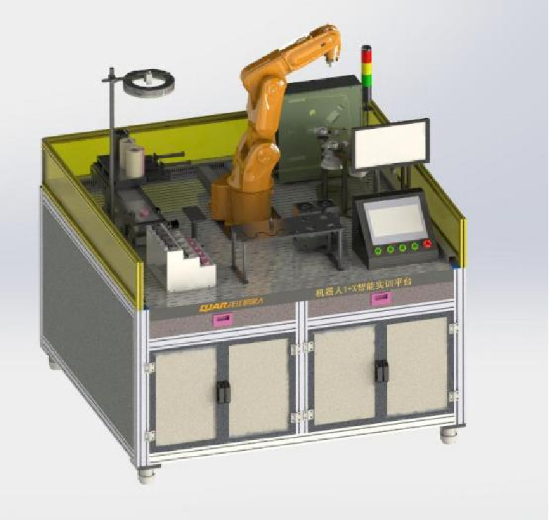
Plan Description Robot Teaching Platform
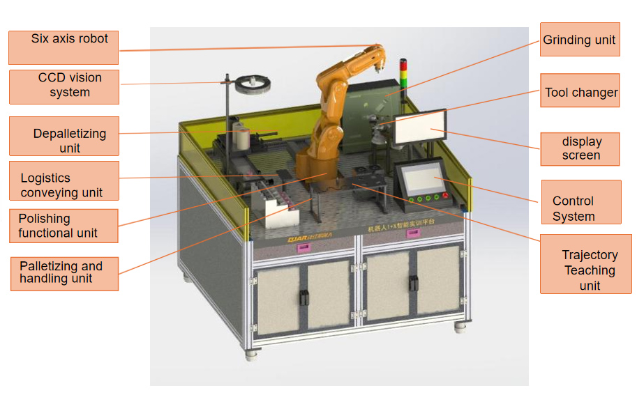
Robot teaching platform: Eleven major modules
1、 Grinding functional unit
2、 Logistics conveying unit
3、 Depalletizing functional unit
4、 Palletizing and handling unit
5、 Polishing functional unit
6、 Trajectory teaching unit
7、 Tool quick change system
8、 CCD vision system
9、electrical control system
10、 Pneumatic Control
11、 Offline programming simulation
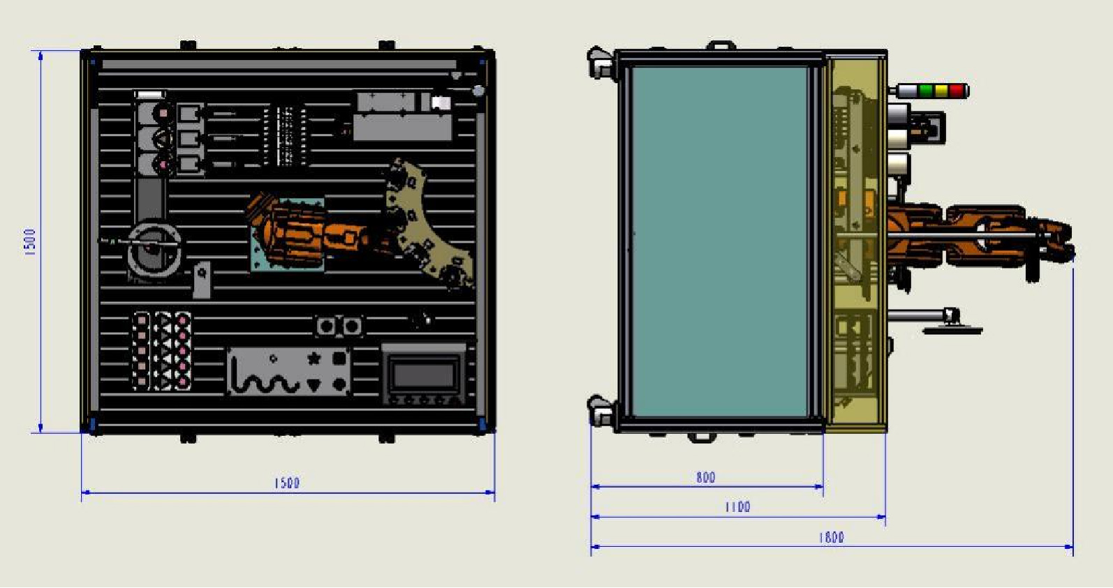
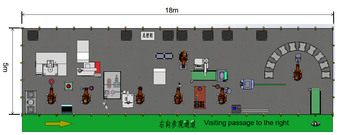
Plan Description Overall Layout Dimension Diagram
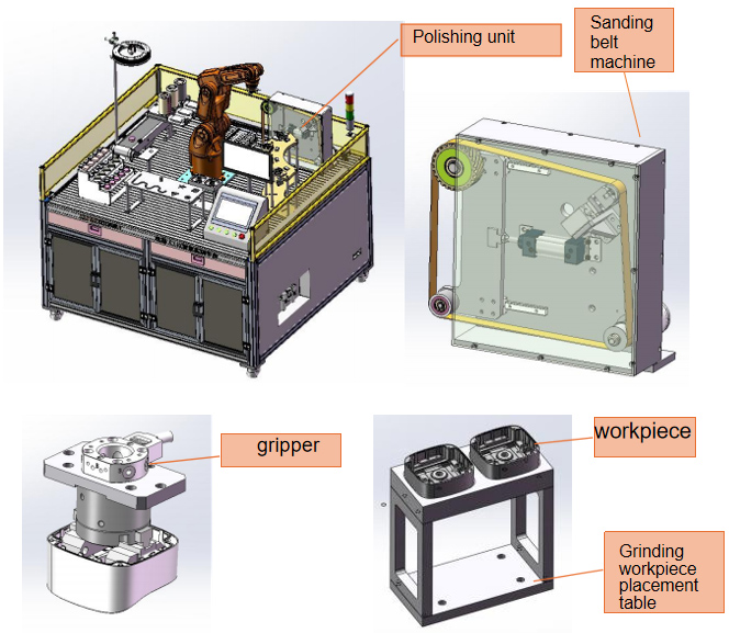
Plan Description Polishing Functional Unit
Introduction to Grinding Function Units
The grinding unit is composed of: belt sanding machine, grinding gripper, grinding workpiece placement table, workpiece (select the aluminum alloy die-casting box in the security industry as the grinding sample) and other modules.
Workflow
1. Robot polishing gripper grabs workpiece from placement table.
2. Robot moves to the sanding belt machine.
3. Select the belt then start the sanding belt machine.
4. The robot moves the workpiece closer to the sanding belt machine to polish the surface of the workpiece.
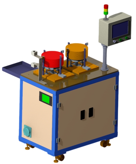
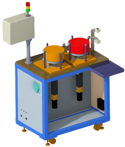
Plan Description Depalletizing Functional Unit
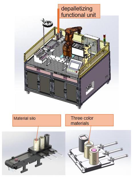
Introduction to the Depalletizing Function Unit
The depalletizing unit consists of: three-color materials (respectively: square, triangle, circle), silo, cylinder, push plate, material distribution mechanism, ejection mechanism and other modules.
Workflow
1. Three colored materials are placed in the silo, and each silo can stack 10 pieces of materials.
2. The cylinder push the plate out of the silo.
3. Cylinder retraction, material move down.
4. The pushed material falls onto the belt.
5. Cycle in sequence until the entire stack of materials is unpacked and completed.
After Sale Services for robotics engineering education platform
Environmental parameters for robotics engineering education platform
Remarks on project environment parameter conditions for Educational Robots
Temperature 17℃ ~25℃ (during operation) 0℃ ~60℃ (during transportation) Allowable range 15℃ ~40℃ Ideal temperature difference ±2℃ for Educational Robots
Humidity: 40% ~70% at 20℃, no condensation for Educational Robots
Vibration below 0.5G for Educational Robots
Installation place for robotics engineering education platform
The Educational Robots must not be installed in areas exposed to radiation such as microwaves, ultraviolet rays, lasers or X-rays.
In order to ensure the grinding accuracy of the Educational Robots and reduce the temperature difference around the equipment, please do not install it in the following areas:
1. Direct sunlight
2. High humidity
3. Large temperature difference
4. Vibration
Strong magnetic field Avoid the following conditions around the Educational Robots installation area:
1. Garage
2. Driveway with frequent car traffic
3. Pressure or stamping equipment
4. Electric welding, spot welding or argon arc welding
5. Substation
6. High voltage lines
Warranty Period and After-sales for robotics engineering education platform
Installation site for Educational Robots
The foundation of the Educational Robots installation site must be fully compacted. There are no holes, empty soil and other bad foundation phenomena.
The Educational Robots installation site must have a fixed power supply that meets relevant national requirements, and temporary power supplies are not allowed. It must be ensured that the Educational Robots have
Good ground protection.
Power requirements for robotics engineering education platform
The power supply provided at the Educational Robots installation site must be a three-phase four-wire system. Line voltage 380V± 5%.
If the three-phase four-wire power line voltage provided by the Educational Robots site is 200V ± 5%. When the Educational Robots are connected to power, it is no longer necessary to connect them through a transformer.
If the three-phase four-wire power line voltage provided by the Educational Robots site is 220V. After the Educational Robots are connected to the power supply, attention should be paid to the voltage stabilization of the power supply, and it must be ensured that the power supply voltage fluctuation does not exceed 220V +5%.
Compressed air for Educational Robots
The main pipeline of compressed air must be equipped with main pipeline filters and dryers. The air pressure must be guaranteed to be 0.6 ~0.7Mpa, and the gas flow rate must be 5 cubic meters/hour. The installation location of the Educational Robots must have a stable air source. The compressed air provided must be dry and clean and comply with relevant national regulations.
Project Implementation Warranty Period and After-sales
All robotics engineering education platform equipment and parts produced by us have a one-year warranty from the date of shipment. Mechanical and electrical parts of robotics engineering education platform that fail due to defects in materials or workmanship will be replaced free of charge after approval. The transportation condition is your company’s factory.
We shall uphold the original manufacturer’s product warranty guarantee for robotics engineering education platform in relation to components utilized or installed in our products that are not produced by us.
We have developed a comprehensive after-sales service system for robotics engineering education platform and offer 24/7 uninterrupted service standards. Global after-sales service for robotics engineering education platform is handled by a highly qualified and trained service crew.
C2M Intelligent Teaching Production Line Solution
(high configuration version v6)
Plan Description: Overall process layout
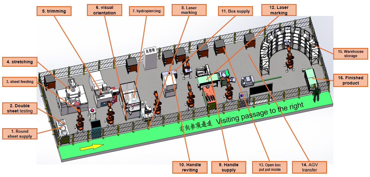
Equipment overall layout
Working flow description
Note: The blank material bin is set with an empty material alarm
and the finished product conveying line is set with a full material alarm.
1. Manually fill the corresponding material silos with materials such as round sheets, handles, boxes, etc., and press the start button on the main console to start the entire line.
2. The silo lifts the round sheets, and the robot grabs the sheets and moves them to the double sheet inspection. After the single sheet is inspected and confirmed, the robot moves to the hydraulic press, and the robot gripper grabs the OP10 product, and then places the sheets on the hydraulic press, the robot places the OP10 product on the transfer table.
3. The robot grabs the OP10 product from the turntable and moves it to the vertical lathe. The robot takes out the OP20 product from the lathe, and then places the OP10 product in the gripper on the lathe. The robot places the OP20 product into the visual punching machine
4. The robot on the visual punching machine takes the OP20 product to the hydraulic punching machine for punching. After punching, the robot places the OP30 on the laser marking machine for marking.
5. After the OP40 product is marked, the robot will grab the OP40 and place it on the CCD to visually take pictures and identify the through holes on the product.
6. One robot grabs the handle from the handle bin, while another robot grabs the non-stick pot and puts it into the hydraulic riveting machine for riveting. After riveting, the robot places the OP50 product on the transfer positioning tool.
7. The robot grabs the color boxes from the color box silo and places them on the color box conveyor line. After the color boxes are transported to the end, they are laser coded.
8. The robot grabs the color box and the finished non-stick pan at the same time. It places the color box on the box opener to open the box. Then the robot places the finished non-stick pan into the color box. After the color box is covered, the robot will The final product + color box is placed on the AGV for output.
9. The AGV transports the finished products to the three-dimensional warehouse, and the robot grabs the products from the AGV and puts them into the three-dimensional warehouse.
Round sheet loading