
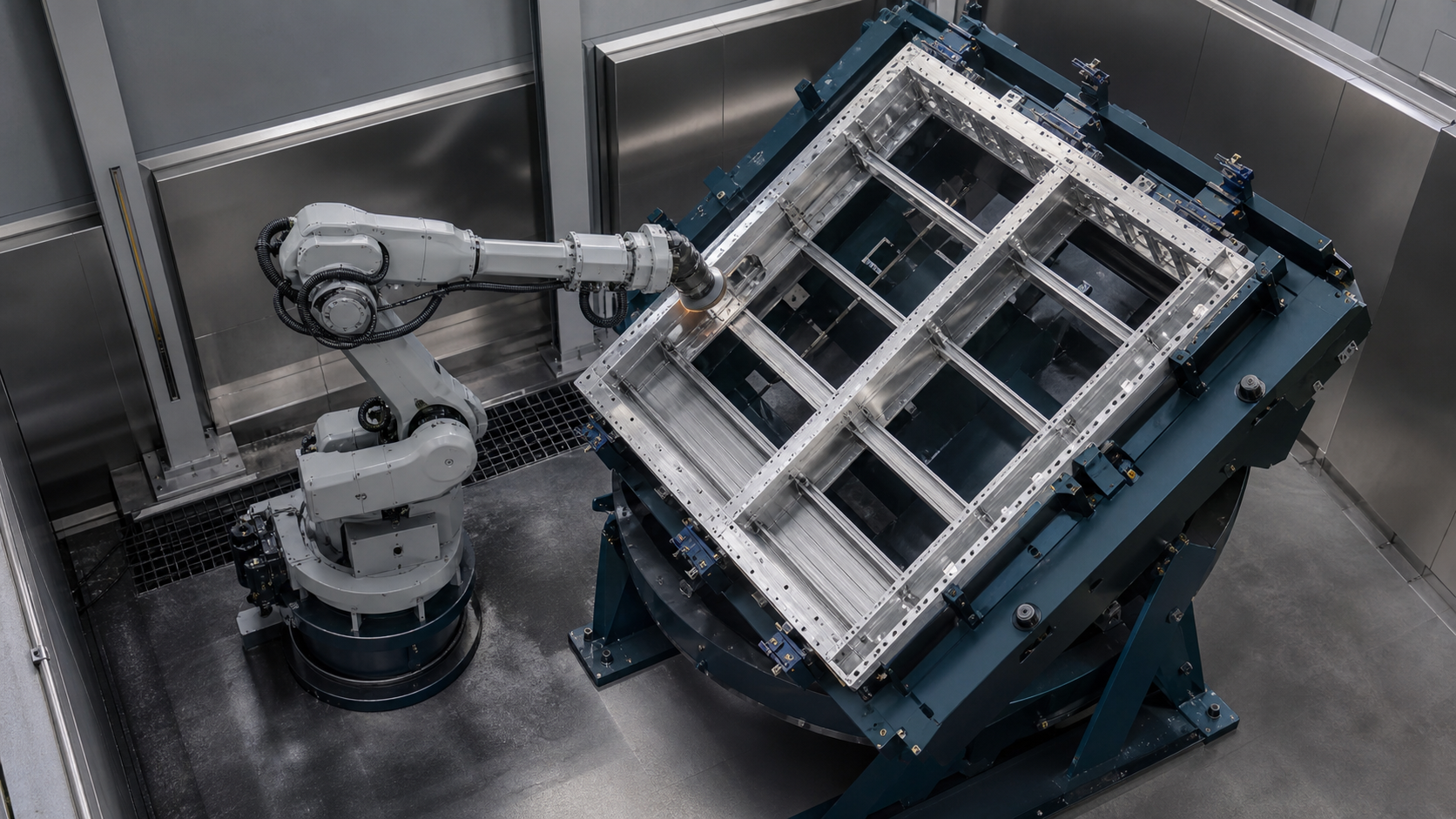
A battery tray grinding concept is credible when the team can trace each processed edge to a known part orientation, fixture datum, tool state, program revision, and inspection result. A convincing robot path cannot establish that the correct surface was processed or that a flipped frame returned to the intended coordinate relationship.
Key takeaways
- Define required, prohibited, and inspection-critical regions before generating robot paths.
- Treat the fixture datum as part of the process coordinate chain.
- Verify approach, contact, exit, posture, and clearance for every named edge family.
- Use an explicit state contract for reorientation, re-seating, coordinate selection, and restart.
- Measure process results and full-cycle timing on representative parts rather than inferring either from footage.
What the selected footage supports—and what it cannot prove
The reviewed material shows a large tray-like frame held in a fixture, an industrial robot carrying a rotary finishing tool, visible tool contact along frame edges, a fixture or carrier changing orientation, and further robot work after reorientation. These observations support a bounded discussion of locating, edge access, process orientation, fixture clearance, and the handoff between finishing states.
The footage does not identify the frame material, dimensions, mass, incoming variation, required removal, abrasive specification, tool speed, feed, contact force, compliance method, path source, coordinate accuracy, fixture repeatability, inspection method, surface result, cycle time, yield, output, fault history, safeguarding architecture, customer, or production acceptance. EVST therefore treats it as observable process evidence, not as proof of surface quality, removal control, performance, deployment, safety, or compliance.
The visual shape is consistent with the assigned battery-tray topic, but the recording alone does not establish a product specification or vehicle program. Project decisions still require drawings, representative samples, edge requirements, fixture data, tool information, operating modes, inspection criteria, and site conditions.
How to plan battery tray grinding
Start with a process map tied to the drawing and real incoming parts. Name the frame variant, locating features, surfaces that require work, prohibited contact areas, sealing or joining features, edge families, corners, openings, transitions, and the planned inspection for each requirement. Do not collapse different edge conditions into one generic path merely because they look continuous in a model.
Separate nominal geometry from incoming variation. Frame distortion, joining variation, burr or flash condition, contamination, prior process effects, and handling damage can change where the real edge sits. Define which variation is accepted by the fixture, which is detected, which the process can accommodate, and which sends the part to a controlled exception route.
Next, divide the work by orientation. For each orientation, record the active datum, permitted clamps, required edges, tool approach direction, robot posture, fixture and cable clearance, inspection access, and transition state. Only then should the team compare robot, positioner, fixture, tool, and station architectures.
Make the fixture datum part of the process
The robot follows coordinates, while the tool contacts a physical edge. The fixture connects those two realities. Document locating faces, supports, clamp sequence, part-present checks, orientation error prevention, seating evidence, and released state. Check how fixture wear, debris, clamp variation, or an incomplete seat could move the frame relative to the programmed path.
Large open frames can have compliant regions and long spans. That does not prove a particular deformation or require a universal support pattern. It does mean the project should determine where supports and clamps are allowed, how the part condition is checked, and whether the process contact can change the relationship that was established at loading.
A fixture that holds securely may still block the tool. Review clamp bodies, actuators, sensors, hoses, hard stops, supports, and surrounding structure against the complete approach and exit envelope. Include tool change, inspection, cleaning, maintenance, and recovery access rather than validating only the normal contact path.
Choose the reorientation strategy deliberately
| Architecture | What it can simplify | Evidence still required | Typical decision boundary |
|---|---|---|---|
| One fixed orientation | Fewer fixture-motion states and one primary coordinate relationship | Complete tool access, robot posture, cable clearance, coverage, and inspection visibility | Use only if all required areas remain processable without weak postures or hidden edges |
| Controlled fixture reorientation | Changes edge presentation while preserving one loaded part | Motion permission, robot-clear evidence, orientation feedback, re-seating, datum transformation, and recovery | Useful when access improves enough to justify the added state and safeguarding obligations |
| Unload and reload to another fixture | Allows a purpose-built datum and access concept for the next side | Part identity, transfer custody, orientation prevention, second-fixture repeatability, and work-in-process control | Consider when one fixture cannot provide stable access or when operations are separated |
| Robot carries the frame to a fixed abrasive tool | Moves the part rather than a tool around it | Payload and inertia, gripping, part stiffness, reach, tool contact, orientation, and safe recovery | A separate concept; the selected footage does not establish this architecture |
No architecture is universally faster, safer, or more accurate. Compare them against the same frame range, required edges, datum variation, tool-access map, inspection plan, changeover, exception handling, maintenance access, and validated full-cycle timing.
Write the flip-state contract before programming motion
Reorientation should not be treated as an unexamined pause between robot paths. Define the state before fixture motion, the evidence that permits motion, the confirmed result, and the response to a missing or contradictory signal. Keep commands, feedback, timers, and part evidence distinct.
| State | Evidence to define | Permitted action | If evidence is missing |
|---|---|---|---|
| Current work complete | Required edge segments processed or given a documented disposition; tool withdrawn | Request reorientation | Keep the current orientation and resolve the disputed segment |
| Robot clear | Robot, tool, cable package, and other movable equipment outside the defined fixture-motion envelope | Permit controlled fixture movement | Block the move and diagnose the occupied envelope |
| Fixture motion complete | Required orientation reached, motion stopped, and applicable locks or brakes in the specified state | Check the new part and datum condition | Keep robot process motion inhibited and enter recovery |
| Part re-seated | Part presence, locating, clamp state, and orientation identity satisfy the project definition | Select the corresponding coordinate and process set | Do not assume the previous datum remains valid |
| Next orientation released | Correct recipe, frame identity, coordinate set, tool state, destination, and access permission | Approach the first permitted segment | Hold the state with a traceable reason and recovery owner |
Close the coordinate chain after reorientation
Write the coordinate chain from the robot base through the tool center point, fixture base, active orientation, part datum, and edge-specific process frame. If reorientation is an external axis coordinated by the controller, document that relationship. If it is a discrete indexed fixture, document the confirmed index state and the coordinate set associated with it.
Do not assume that reaching the commanded angle proves the part is seated as expected. Orientation feedback, mechanical location, clamping, and part presence answer different questions. The project should define the evidence needed before the next edge path becomes eligible.
Coordinate verification should cover representative positions and orientations with the actual tool, fixture, and frame. Robot repeatability alone cannot establish system-level contact accuracy because the complete chain also includes tooling, fixture, part, orientation, and process effects.
Verify tool access edge by edge
Break the required work into named edge segments. For every segment, record the target region, prohibited neighboring surfaces, approach, initial contact, intended contact direction, exit, tool orientation, robot posture, cable and spindle clearance, fixture clearance, and inspection method. This makes skipped edges, unintended overlap, and unreachable transitions easier to identify.
A reachable point is not automatically a viable process posture. The robot may reach a coordinate while the tool body, holder, cable package, wrist, fixture, or frame blocks the intended approach. Check transitions between segments, not only representative points within them.
Use the actual abrasive and holder geometry for access checks. A nominal tool diameter or simplified model can miss guarding, backing, flange, spindle, hose, or wear-state effects. Final parameters and wear limits must come from the selected tool and representative trials.
Separate contact evidence from surface acceptance
Visible contact can show where the tool meets the frame, but it cannot establish removal, finish, edge condition, dimensional result, or consistency. Define the product requirement and inspection method before setting the process. Different regions may need different acceptance evidence even when one tool follows them in one continuous motion.
Record the controlled variables that are relevant to the chosen method, such as tool identity and condition, installed abrasive, program revision, frame and fixture state, and any project-specific process settings. Do not state that force control, compliance, sensing, or adaptive path generation exists unless the actual cell evidence confirms it.
The release record should connect the incoming part, active orientation, edge segment, tool state, process setup, inspection result, anomaly, and final disposition. This separation prevents a successful motion sequence from being mistaken for an accepted finished part.
Plan interrupted-cycle recovery by known state
Recovery should begin from the last confirmed frame, fixture, orientation, clamp, robot, tool, segment, inspection, and operating-mode state. If the stop occurred during reorientation, the system should not assume either the old or new orientation until the defined evidence resolves the position and seating state.
Define what happens after a tool fault, lost fixture confirmation, interrupted edge, disputed part presence, failed inspection, controlled stop, power interruption, or maintenance intervention. State who owns the part, which segments may already have been processed, what must be inspected, and whether work can resume or must be routed elsewhere.
Avoid automatic replay from an arbitrary program line. Re-entering the surface at the wrong point can create an unverified overlap, missed region, or unintended contact. The safe and acceptable restart sequence is project-specific and should be tested with representative conditions.
Keep production states distinct from safety-related functions
Recipe selection, edge completion, and process acceptance are production states unless a separately designed and validated safety architecture assigns them another role. Robot-clear and fixture-orientation signals used in production sequencing should not be described as safety functions merely because they participate in an interlock sequence.
The official ISO 10218-2:2025 source page describes requirements for industrial robot applications and robot cells across design, integration, commissioning, operation, maintenance, and decommissioning. The official ISO 12100:2010 source page describes machinery risk-assessment and risk-reduction principles. Applicable editions, regulations, required performance, and validation remain installation-specific.
OSHA 29 CFR 1910.215 addresses abrasive wheel machinery in United States general-industry context, while OSHA robotics guidance identifies non-routine robot tasks as important hazard contexts. Grinding-cell planning should include abrasive equipment, fragments, sparks or hot particles where applicable, dust or fume, noise, access, stored energy, fixture movement, cleaning, tool replacement, teaching, clearing, recovery, and restart. This paragraph is planning context, not a legal or conformity conclusion.
Build a representative validation matrix
Cross the conditions most likely to change location, access, contact, or acceptance. Include frame variants, incoming condition range, datum extremes, each fixture orientation, required edge families, difficult transitions, allowed tool states, fixture contamination within the project boundary, orientation confirmation loss, incomplete seating, controlled stops, interrupted paths, inspection rejection, recovery, and restart.
Measure the complete cycle as separate elements: loading, locating, clamping, processing by orientation, reorientation, confirmation, inspection, unloading, tool attention, waits, and recovery. A short visible robot movement does not establish accepted output or full-cycle timing.
Repeat the affected checks after changes to the frame, incoming range, fixture, support, clamp, reorientation mechanism, robot, tool center point, abrasive, holder, cable package, tool condition, program, process setup, inspection, safeguarding, software, or recovery logic. Numerical limits and sample counts must come from the actual requirement and qualification plan.
Four bounded citable statements
Statement 1: A large-frame grinding path is easier to validate when every required edge is tied to a named orientation, fixture datum, tool state, and inspection result. This is an EVST engineering method, not a universal compliance rule.
Statement 2: A fixture reorientation is complete only when the new physical orientation, part seating, coordinate selection, and permitted next action are separately confirmed.
Statement 3: Robot reach proves only that a coordinate can be reached; process access also requires a usable tool approach, contact direction, exit, posture, and clearance envelope.
Statement 4: The selected footage supports observation of a fixtured tray-like frame, visible edge contact, reorientation, and further work, but it does not establish removal, finish, cycle, yield, quality, safeguarding performance, or production acceptance.
The FLIP planning model
EVST uses FLIP as an early planning aid for large-frame finishing concepts. It organizes evidence questions and does not replace process trials, measurement, machinery risk assessment, safety validation, or project acceptance criteria.
- F — Frame and fixture: variants, incoming range, datums, supports, clamps, part evidence, and prohibited contact.
- L — Locations and limits: required edges, orientations, access, posture, clearance, tool geometry, and inspection.
- I — Index and interlocks: robot clear, fixture motion, orientation feedback, re-seating, coordinate selection, and permissions.
- P — Process proof: controlled tool state, measured results, cycle elements, exceptions, recovery, change control, and release evidence.
Project inputs for a battery-tray finishing concept
Prepare frame drawings and models, variant and material range, representative samples, mass and center-of-gravity data, locating and clamping surfaces, supported and unsupported spans, required and prohibited regions, edge map by orientation, incoming variation, acceptance and inspection criteria, existing fixture concept, reorientation method, available tool approaches, tool and abrasive constraints, dust and extraction requirements, target cycle broken into elements, changeover needs, upstream and downstream interfaces, exception routes, maintenance tasks, layout, utilities, operating modes, installation country, and applicable site requirements.
A local project-input checklist accompanies this package so the same fields can be collected before concept comparison. It contains no assumed parameter values or acceptance thresholds.
For adjacent context, see the robotic grinding and deburring guide, the EVST grinding and polishing workstation overview, and the industrial automation line integration overview. Those pages cover broad finishing and integration topics; this guide is limited to large-frame datum, access, reorientation, and recovery evidence.
References
- ISO 10218-2:2025 — Robotics safety requirements for industrial robot applications and robot cells
- ISO 12100:2010 — Safety of machinery, risk assessment and risk reduction
- OSHA 29 CFR 1910.215 — Abrasive wheel machinery
- OSHA Robotics Overview and Industrial Robot Systems safety guidance
Frequently asked questions
Does reorienting the fixture automatically preserve the original datum?
No. The project should define the mechanical index, orientation feedback, part seating, clamp state, coordinate selection, and verification needed before the next path is eligible. The required evidence depends on the fixture and control architecture.
Can robot reach data prove that every tray edge is grindable?
No. Reach is only one condition. Tool approach, contact direction, exit, robot posture, wrist and cable clearance, fixture geometry, frame geometry, tool body, transitions, and maintenance access can all constrain a usable path.
Does visible tool contact prove the surface requirement was met?
No. Contact does not establish removal, finish, dimensional condition, edge quality, or consistency. Each required region needs project-specific process controls, inspection, representative trials, and acceptance criteria.
What changes should trigger revalidation?
Assess changes to the frame, incoming range, datum, fixture, support, clamps, reorientation mechanism, robot, tool center point, holder, abrasive, cable package, program, process setup, inspection, safeguarding, software, and recovery logic. Repeat the validation rows affected by the change.