
Robot Grinding of Zinc-Alloy Handles: Parting-Line Removal
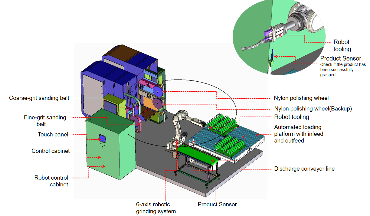
This robot polishing cell consists of a six-axis robot and a four-station belt grinder with a loading and unloading table: parts are ground in sequence from coarse to fine belts, or polished on a nylon wheel.
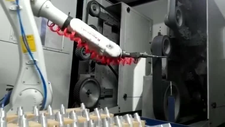
The robot holds the part for stable, efficient grinding
The robot carries the product to the consumable stations for grinding and polishing; for large products the robot holds the tool and works on the fixed part instead.
cell layouts, force-control options and selectionLarge products are ground and polished by a robot-held tool, with automatic changeover of tool consumables.
deburring cells for heavy castingsKey components, arranged around your part
Six-axis robot and grinding fixture
The robot is sized to the grinding process so the sequence runs steadily and continuously.
Consumable stations
Two-, four- or six-station layouts are configured to the grinding process, and the consumables — abrasive belts, flap wheels, nylon wheels, sisal wheels and cloth buffing wheels — are switched to suit the job.
Stacked consumable stations
An upper-and-lower station arrangement shortens robot travel between stations for fast, continuous output.
Loading and unloading device
One-in, one-out: each part returns to its tray position after grinding; when the tray is finished the cell switches to the next tray automatically, and operators load and unload the trays.
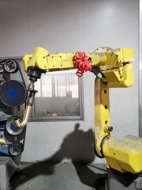
Three grinding-tool mounting options
Fixed mount
The grinding tool is rigidly bolted to the robot flange for a stiff, high-strength connection.
cell layouts, force-control options and selectionFloating mount
The grinding tool floats to follow the product surface, giving a flatter, more even finish.
cell layouts, force-control options and selectionFloating mount with torque sensing
The tool follows the product surface with a steady force output for curved faces, corners, very thin parts and high-specification parts.
cell layouts, force-control options and selectionMany product types, one grinding process
Sanitary ware: faucets and shower fittings
Zinc-alloy faucet covers, copper-alloy faucet bodies, stainless steel faucets, curved spouts and shower arms suit the part-held finishing route. The workpiece moves between fixed stations as the robot presents the required surfaces to the tool.
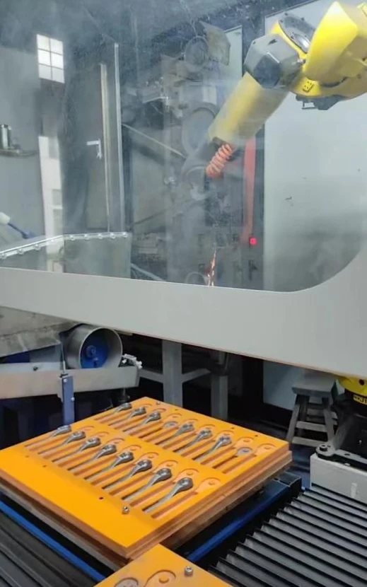
Hardware tools: handles and wrenches
Door handles and tool-steel wrenches are typical applications. Shaped tray positions organize the incoming parts, while the gripper carries each part to the abrasive or buffing station. A typical job is parting-line and flash removal on zinc-alloy die-cast handles before polishing.
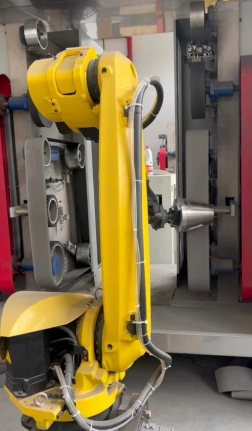
Home appliances: kettle bodies and handles
Stainless steel kettle bodies and aluminum microwave handles represent different part shapes within the same part-held approach: a round, thin-wall body and a long handle. Each needs a gripping arrangement matched to its shape.
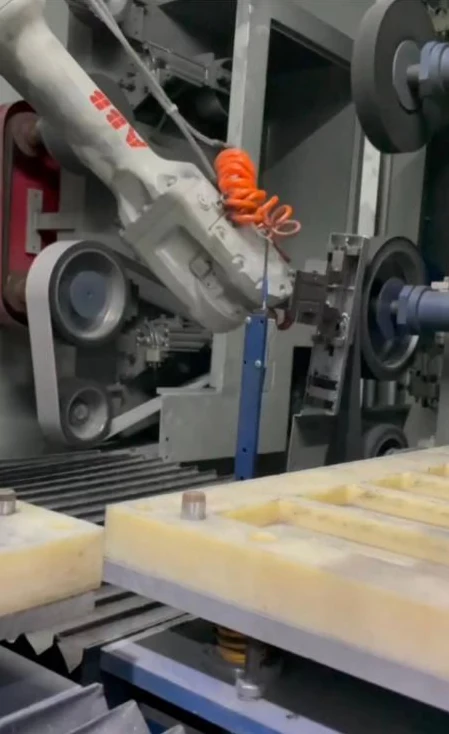
Smart locks: small covers and long components
Zinc-alloy smart-lock covers can be presented in locating trays. Enclosed cell layouts are also available for long cover and handle-type components, with the robot working inside the machine enclosure.
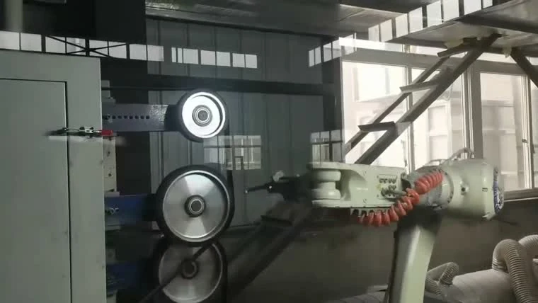
Motorcycle components: brake levers and frames
Aluminum handbrake and brake levers are carried past fixed contact wheels for grinding and polishing. Welded tubular rear frames are another typical part family, using a workpiece-specific holding arrangement. Typical aluminum die-cast parts for grinding and polishing include wheel hubs, luggage racks, mirror housings, rear racks, fuel tanks, shock absorber bodies and footpegs.
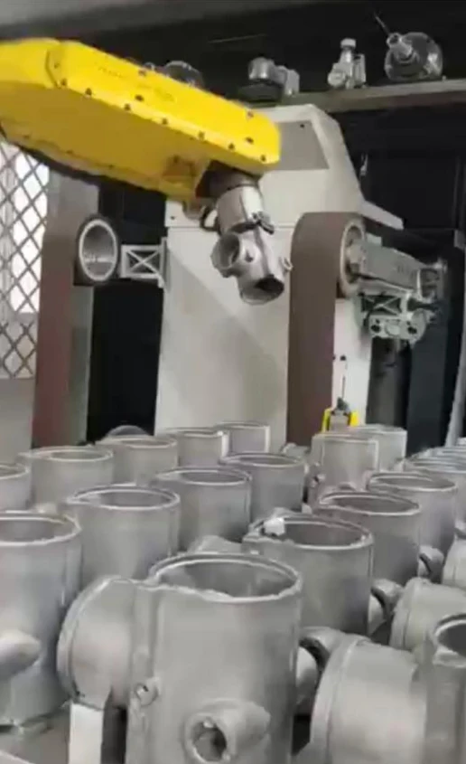
Valves and castings: aluminum valve bodies and cast housings
Aluminum three-way and four-way valve bodies, together with flat aluminum cast housings, are typical deburring applications for this route. The robot holds the part and brings the required edges to fixed finishing equipment.
Grinding method configured to the product
Use the workpiece family to start a layout discussion. The combinations below are configuration examples, rather than a universal equipment specification.
| Workpiece family | Holding method | Station combination | Loading arrangement | Typical process |
|---|---|---|---|---|
| Sanitary faucets and fittings | Robot grips the product | Abrasive belt, nylon wheel and cloth wheel | Locating trays | Grinding and polishing |
| Door handles and smart-lock covers | Robot grips the product | Abrasive belt, nylon wheel and cloth wheel | Shaped tray array | Grinding and polishing |
| Wrenches and hardware | Robot grips the product | Abrasive belt, nylon wheel and cloth wheel | Row-arranged loading trays | Grinding and polishing |
| Kettle bodies, sleeves and bushings | Robot grips the product | Abrasive belt, nylon wheel and cloth wheel | Workpiece-matched trays | Grinding and polishing |
| Aluminum die-cast brake levers and rear racks | Robot grips the product | Abrasive belt, nylon wheel and cloth wheel | Locating tray or fixture | Grinding and polishing |
| Aluminum valve bodies and cast housings | Robot grips the product | Abrasive belt, nylon wheel and cloth wheel | Batch loading from bins | Grinding and deburring |
Provide product drawings or photos and your current manual grinding and polishing process, and we can plan the equipment and process.
Talk through a cell layoutKeep small parts ready for pickup
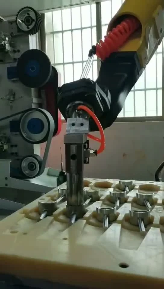
An enclosed working area
The whole layout sits within the robot's working range, and a wet vacuum dust extractor is fitted to clean dust from the air.
cell layouts, force-control options and selection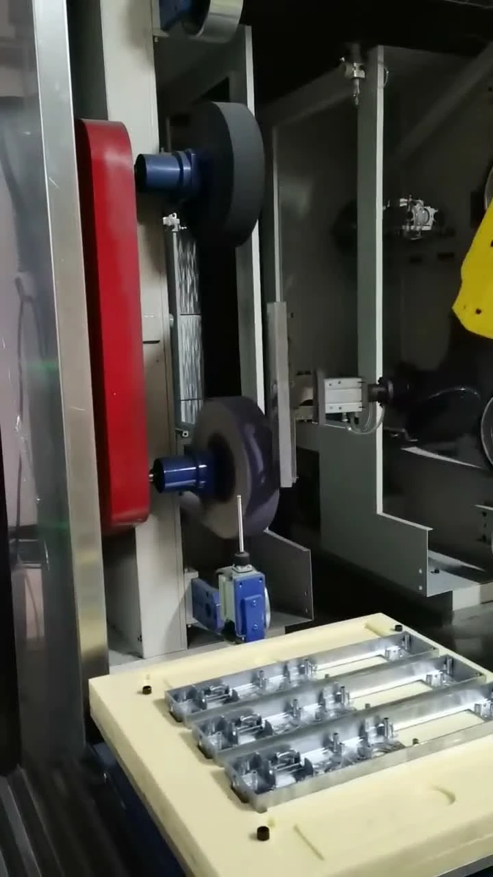
Why a part-held cell
Consistency
A programmed path presents the workpiece to fixed finishing stations in a repeatable sequence; gripping and consumable condition remain part of process setup.
Safety
Separate loading and finishing positions can help keep operators away from the tool during processing, with guarding and access planned for the cell.
Throughput
Organized trays and loading positions can support a steady flow of parts. Output depends on the workpiece, finishing steps and loading arrangement.
Questions before specifying a cell
Which parts suit a part-held cell rather than a tool-held cell?
Hardware that can be securely gripped and brought to fixed finishing positions is the focus of this page. For larger parts, the arrangement can be reversed so that the part stays fixed and the robot carries the tool.
What consumable stations can one cell combine?
A cell can combine fixed abrasive and buffing positions around the robot. The required finishing steps determine the station combination; the equipment layout is matched to the workpiece.
How are small parts loaded — trays, lift magazines or a conveyor?
Locating trays and lift magazines are available arrangements for small parts. Alternating loading positions and double-layer material tables are further layout options. A conveyor interface can be discussed when the upstream process calls for one.
Can one cell run several part numbers without rebuilding the fixture?
Do not assume that different part numbers share the same fixture. Compare their gripping surfaces, locating points and finishing paths first. Send drawings or samples so the common features and required changeover work can be assessed.
Which finishing steps does the cell cover — deburring, grinding, buffing?
The part-held route covers grinding and polishing of hardware and deburring of suitable aluminum cast parts. Buffing positions can be included for the required finish. The sequence is selected for the material, geometry and finish target.
Define the part. Discuss the finishing route.
Share a drawing or sample, the material, the surfaces to be finished and the desired result. EVST can discuss the gripping arrangement, station combination and loading approach around that information.