Present components correctly
Orient, separate and deliver parts to a stable pick or loading position.

Connect feeding, pressing, joining, greasing, torque verification, error proofing, traceability and palletizing around the actual part family.
The final configuration follows the workpiece, process sequence, inspection boundary and plant material flow.
Ball joints, control arms and stabilizer links combine precise component orientation with pressing, lubrication, torque-related checks, sealing or functional verification. The process order and inspection boundary should stay tied to each workpiece instead of being copied across unrelated parts.
A complete route is assembled from process groups, then reviewed for interfaces and quality decisions.
Orient, separate and deliver parts to a stable pick or loading position.
Apply press-fitting, rolling or other joining steps in the required order.
Coordinate quantitative greasing and mouth greasing with later assembly steps.
Use swing, rotation or oscillation torque control and applicable sealing checks.
Confirm presence, orientation and results, then define the record fields the project requires.
Transfer finished parts into the agreed pallet, tray or downstream interface.
Stations follow a direct route when the process sequence and plant flow support progressive movement.
A compact indexed arrangement can suit short, repeatable sequences with controlled station-to-station movement.
Robotic handling can connect processes where orientation, reach or product variation needs more adaptable motion.
Keep operator loading, replenishment or selected judgments where presentation varies or the business case does not support automatic handling.
Connect stable feeding, repeatable processing, automatic checks and material transfer when part conditions and interfaces are controlled.
Quality controls should follow the actual process risk and connect results to the next material-flow decision.
Confirm that the correct component is available and positioned for the operation.
Monitor the defined pressing, greasing, joining or torque-related conditions.
Use applicable torque, sealing or online function checks to decide the route.
Specify which identifiers, events and results must be stored and exchanged.
Traceability scope is defined during the project; the page does not assume that every event or result is recorded.
Each case keeps its process description attached to the correct component family.
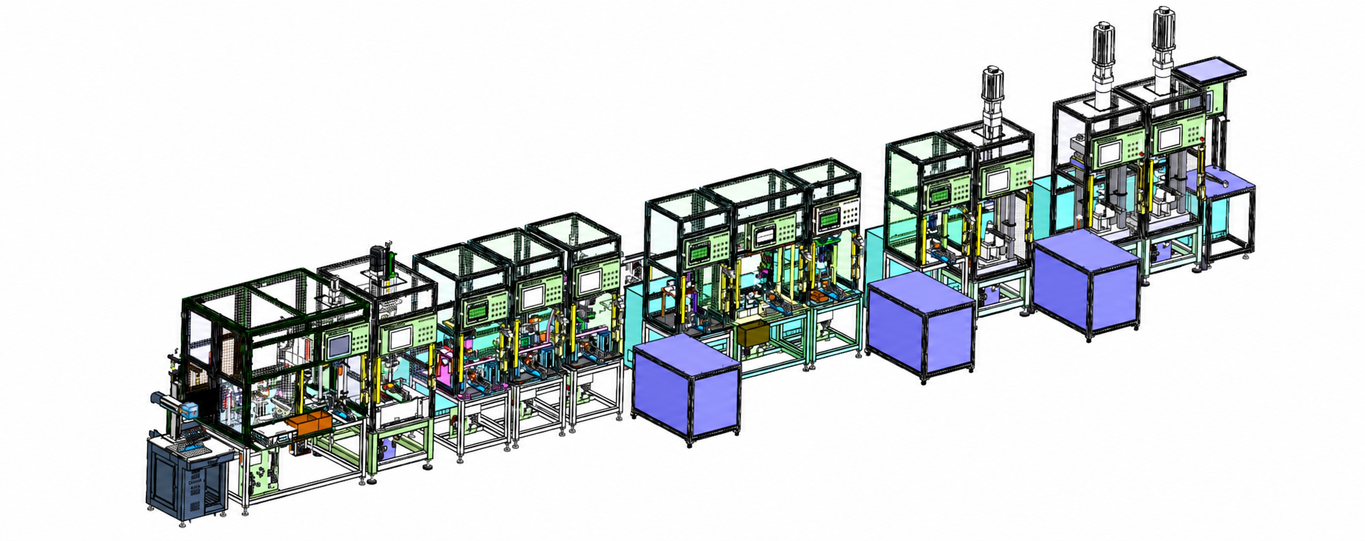
Illustrative sequence: quantitative greasing → component press-fitting → rolling → pre-swing → swing torque test → rotation torque test → mouth greasing → dust cover assembly → ring assembly → dust cover sealing test → bushing press fitting.
Assembly focus: Maintain part orientation and keep lubrication, mechanical assembly and verification in the correct order.
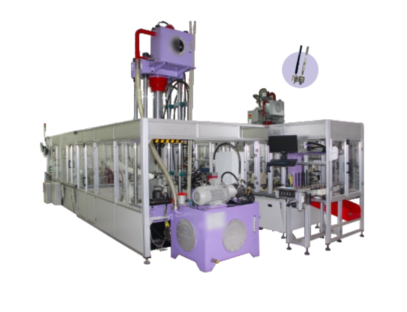
Illustrative sequence: automatic component feeding → servo-hydraulic pressing → torque control → robotized palletizing.
Assembly focus: Stabilize presentation before pressing, then connect the defined torque result to the material route.
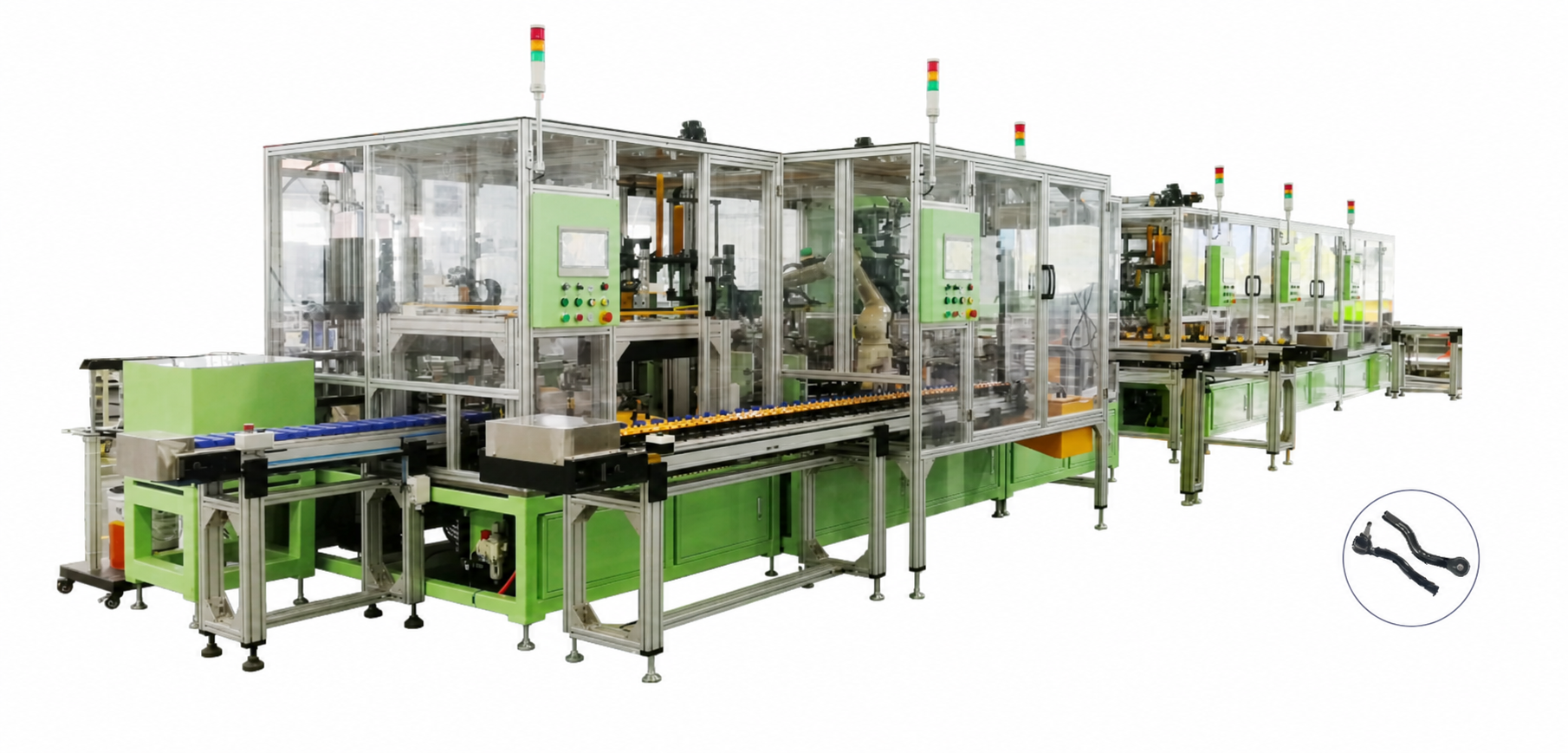
Illustrative sequence: automatic component feeding → oscillation torque control → rotation torque control → robotized palletizing.
Assembly focus: Keep oscillation and rotation checks distinct so each result can drive the intended acceptance decision.
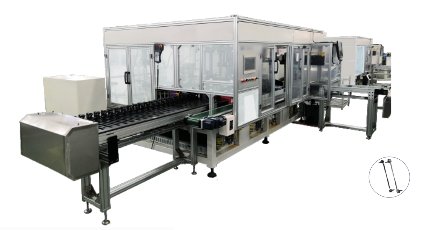
Illustrative sequence: component presentation → defined assembly operations → online function detection → error-proofing decision → downstream transfer.
Assembly focus: Confirm what is checked, how the result is judged and where a nonconforming part is routed.
Keep process order and interlocks aligned with the part.
Place checks where results can still control the route.
Automate repeated handling where interfaces are stable.
Define variants, fixtures and recipes before detailing equipment.
The approach supports automotive suspension and chassis component production, including ball-joint, control-arm and stabilizer-link assembly. Similar planning principles can apply to other metal-component assemblies after the process and acceptance criteria are confirmed.
Review parts, variants, processes, checks, layout and interfaces.
Define station sequence, material flow, controls and acceptance logic.
Build and integrate the approved mechanical, electrical and control scope.
Verify operation against the agreed workpieces and acceptance plan.
Provide project-level documentation, training and after-delivery coordination.
Provide part drawings, variants, incoming condition, process sequence, quality checks, traceability needs, layout constraints, utilities and upstream and downstream interfaces.
No. Automation level should reflect part presentation, repetition, ergonomics, quality risk and the stability of each interface.
Compare the workpiece route, station count, transfer needs, available space, changeover method and inspection flow before selecting a linear, indexed or robotic-cell architecture.
Potentially. The concept review must confirm common locating features, fixture changes, recipes, inspection settings and material-routing rules for every intended variant.
Define the part identifier, required process events, inspection results, timestamps, recipe or variant references and the systems that receive or store those records.
Share the part family, process map, required checks, variant plan and layout constraints so EVST can frame an assembly-line concept around the real application.