
Heavy Duty Welding Robot Workstations for Large and Heavy Parts
A heavy-duty workstation starts with part weight, envelope, rotation, seam access and multipass requirements. This page compares eight arrangements so the project team can narrow workpiece positioning and external motion to an engineering shortlist.
Define the large-part family before choosing equipment motion
Use these workpiece families to frame length, diameter, weight, loading and seam-access requirements.
Use four constraints to decide how the part is presented
Load and envelope
Check workpiece and fixture mass together, then define length, width and rotation diameter.
Rotation and support
Choose headstock-tailstock, double-column or L-positioning concepts against the centre of gravity and support points.
Access and external motion
Consider floor, overhead or inverted movement only when a fixed robot position cannot cover the required length or height.
Multipass process
Contact sensing, arc tracking and multilayer multipass functions are available as optional arc-welding software across the heavy group.
Organize eight options by positioning, travel and overhead access
This is a constraint-driven engineering path, not a matrix of equivalent product cards.
Positioner-led presentation
Start with how the part must rotate or tilt.
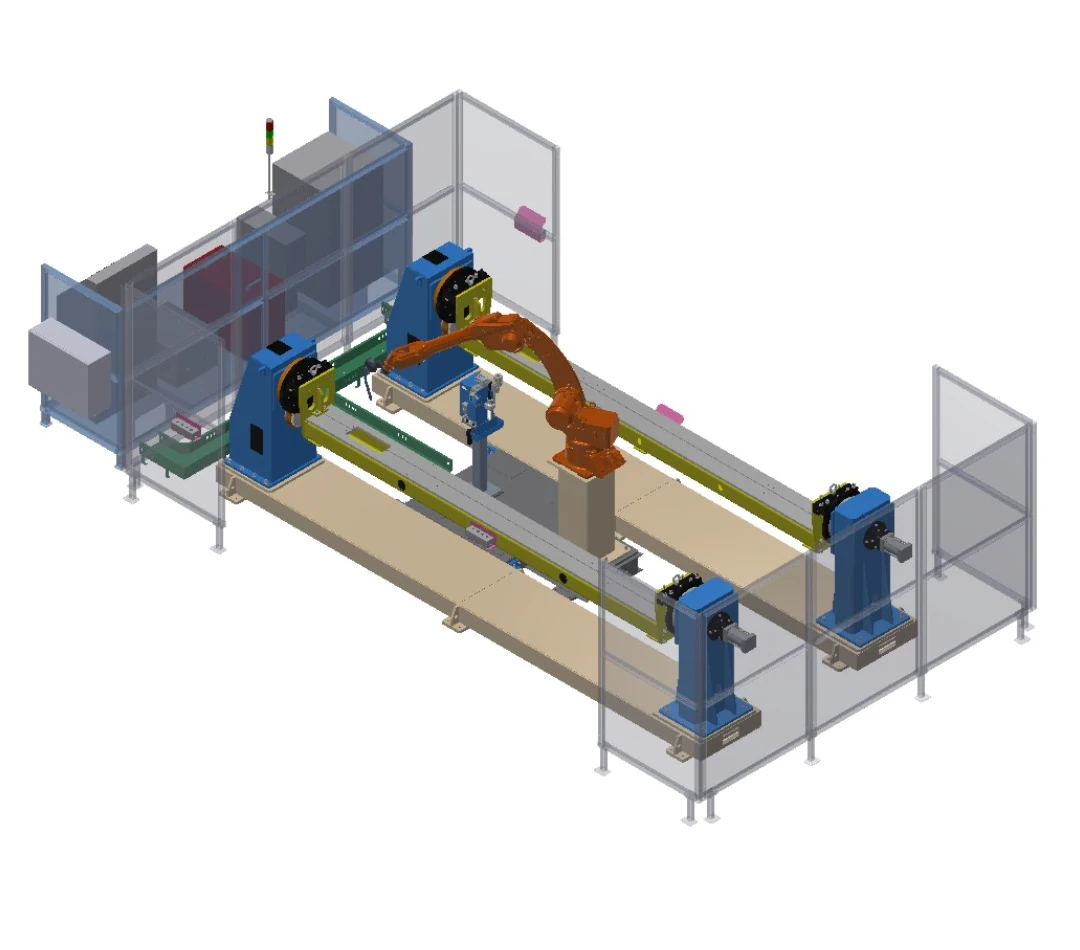
Dual-station headstock-tailstock workstation
Two headstock-tailstock positioners provide alternating part presentation with pneumatic tailstock clamping.
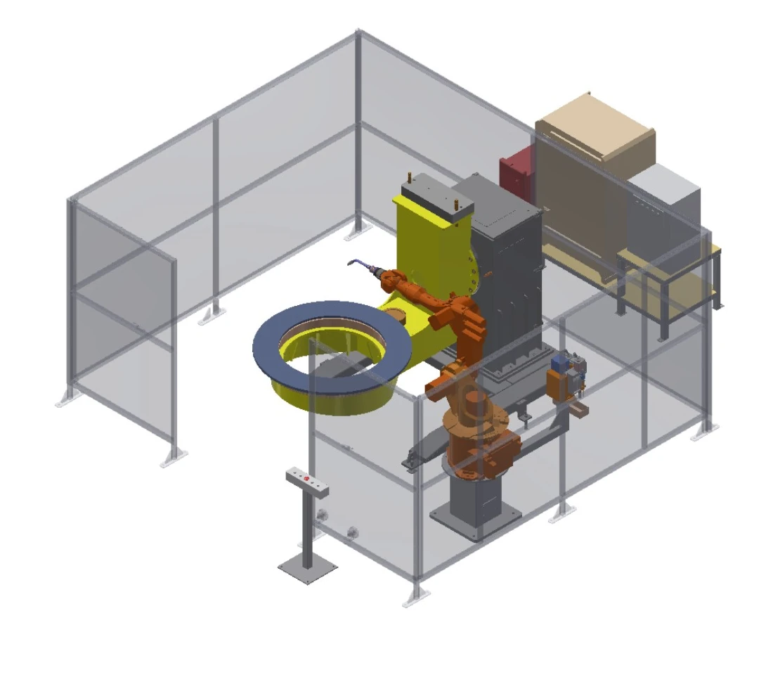
Two-axis L-positioner workstation
A two-axis L positioner rotates and tilts the fixture for multi-face weld access.
Travel-assisted coverage
Add controlled movement when one robot position cannot cover the required length or height.
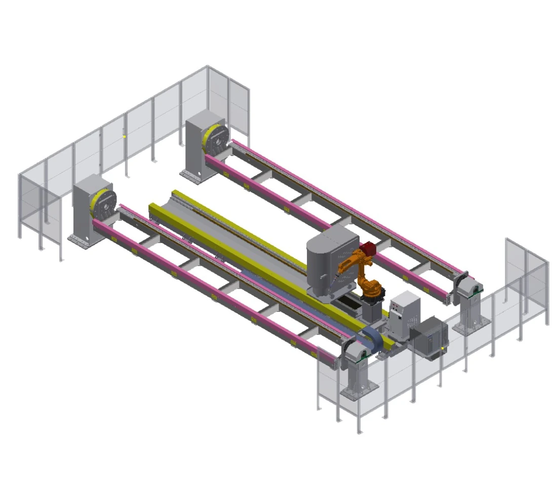
Long-workpiece travel-axis workstation
A floor travel axis extends robot coverage along a six-metre fixture envelope served by two headstock-tailstock positioners.
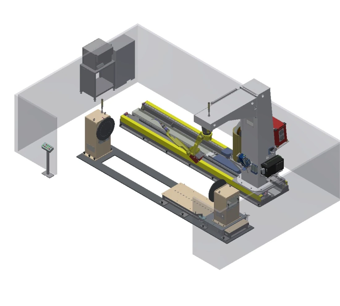
Inverted C-frame travel workstation
An inverted C-frame and travel axis extend access along the part while the tailstock offers length adjustment.
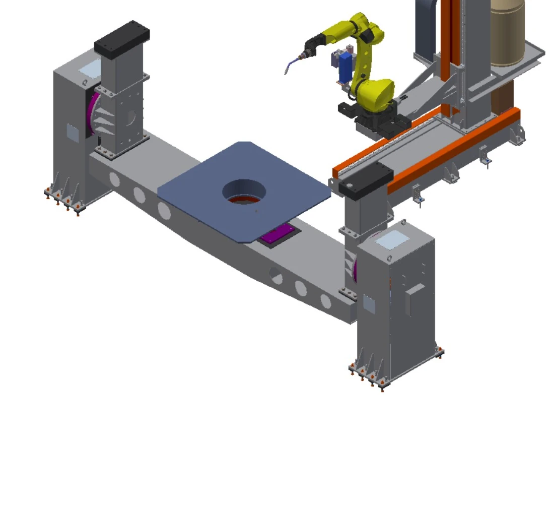
Two-axis floor-travel workstation
Y- and Z-axis movement combines with a double-column positioner rated across a two-to-five-tonne range.
Overhead and inverted access
Move the robot above or around the workpiece when access and clearance drive the architecture.
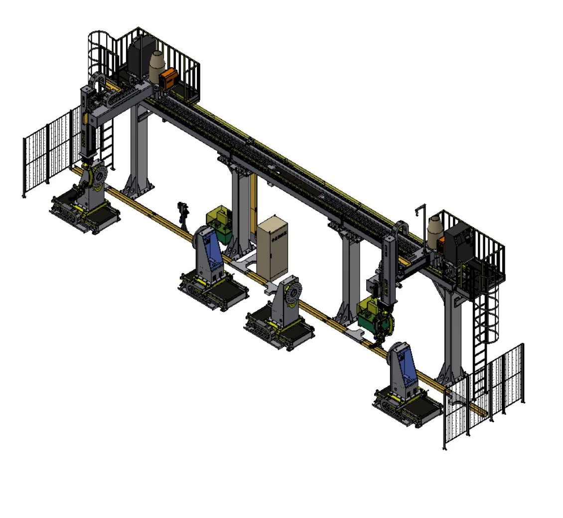
Multi-axis overhead carriage workstation
Selectable overhead motion axes combine with one or two heavy headstock-tailstock positioners for large rotational workpieces.
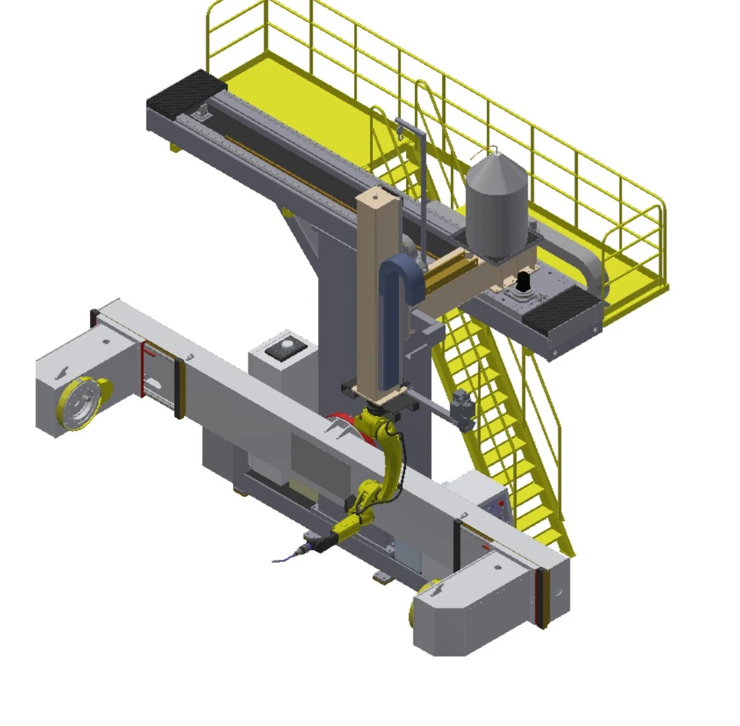
T-shaped overhead carriage workstation
Two-axis overhead movement serves a side-mounted positioner for medium-diameter rotational parts.
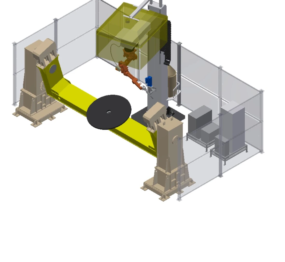
Rotating inverted C-frame workstation
A rotating inverted C-frame adds vertical travel and angular access around the highest positioner load range in this group.
Compare load, envelope, external motion and protection fields
| Row | Descriptive configuration | Arm reach | Positioner load | Workpiece envelope | External motion | Positioning arrangement | Protection field |
|---|---|---|---|---|---|---|---|
| A | Long-workpiece travel-axis workstation | 2 m | 1–3 t | Fixture 6 m × 1.5 m | Travel 5 m | Headstock-tailstock, 2 units | Semi-enclosed fence |
| B | Dual-station headstock-tailstock workstation | 2 m | 1–3 t | Fixture 3 m × 1.5 m | Headstock-tailstock, 2 units | Semi-enclosed fence | |
| C | Inverted C-frame travel workstation | 1.4 m / 2 m optional | 1–3 t | Fixture 4 m × 1 m | Travel 4 m | Headstock-tailstock; tailstock adjust 1.5 m | Semi-enclosed fence |
| D | Two-axis L-positioner workstation | 1.4 m / 2 m optional | 1 t / 2 t optional | Two-axis L positioner | Semi-enclosed fence | ||
| E | Multi-axis overhead carriage workstation | 1.4 m / 2 m optional | 1–5 t | Rotation ≤3 m | X 2–30 m; Y 1–2 m; Z 1–2 m | Headstock-tailstock, 1 or 2 units | Semi-enclosed fence |
| F | T-shaped overhead carriage workstation | 1.4 m / 2 m optional | 1–3 t | Rotation ≤1.8 m | X 3–4 m; Z 1–2 m | Side-mounted headstock-tailstock; adjust 0.5 m | |
| G | Two-axis floor-travel workstation | 1.4 m / 2 m optional | 2–5 t | Rotation ≤3 m | Y 1.5 m; Z 1.5 m | Two-axis double-column; adjust 0.5 m | |
| H | Rotating inverted C-frame workstation | 1.4 m / 2 m optional | 3–10 t | Rotation ≤3 m | Z 1–2 m; rotation ±90° | Two-axis double-column; adjust 0.5 m | Semi-enclosed fence |
Build the protection concept around logistics and external motion
Heavy-part safeguarding is not a standard accessory list. It must be reviewed together with lifting, loading, service tasks, fume control and controlled movement.
Isolation and interlocks
Define protection around maximum movement, positioners, loading zones and personnel entry.
Lifting and large-part access
Confirm crane paths, gates or opening zones, workpiece transfer and abnormal removal.
Fume and process interfaces
Include welding-fume capture, utilities, process media and equipment cooling in the overall concept.
Maintenance and validation
Provide controlled conditions for service, torch cleaning, fixture adjustment and safety-function validation.
Define part positioning and the seam map before equipment scope
Part review
Drawings, mass, centre of gravity, joints, variants and incoming condition.
Positioning concept
Support, rotation, loading and fixture-interface boundaries.
Access study
Robot posture, external motion, collision and service access.
Process and protection
Weld procedure, sensing, fumes, interlocks and personnel interaction.
Acceptance definition
Agree parts, seams, test conditions, documents and decision method.
Four heavy welding scenarios with different constraints
Cases illustrate part families, arrangement and process focus only; they do not identify a customer, fixed equipment package or performance promise.
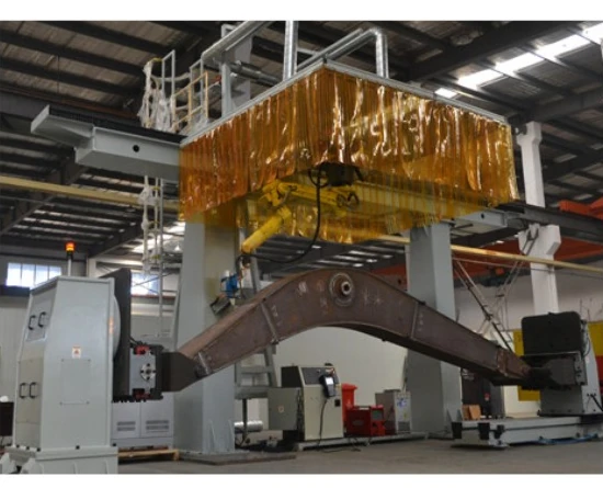
Construction equipment booms and beams
Support long fabricated sections, coordinate external motion and keep weld access tied to the actual joint map.
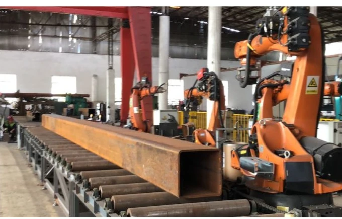
Steel structure sections
Plan multi-side access for box sections and structural profiles without treating one fixture as universal.
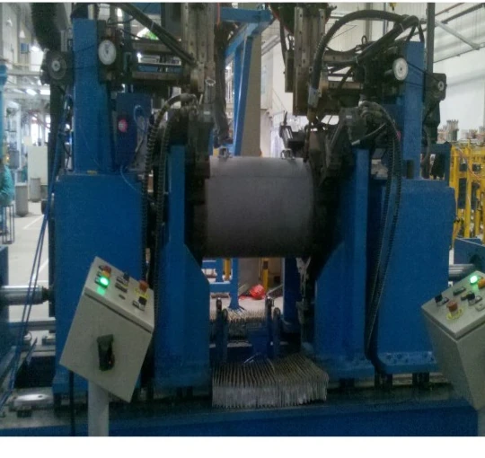
Pressure-vessel shells
Use controlled rotational presentation for cylindrical seams while confirming diameter, support and loading method.
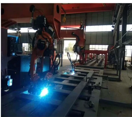
Commercial-vehicle fabrications
Separate tanks, frames and body structures into clear part families before selecting workholding and station flow.
Engineering questions to close before concept design
How is the capacity range screened?
Provide workpiece mass, fixture mass, centre of gravity, support method and dynamic orientation. Project engineering calculations determine the applicable range.
When should external robot motion be considered?
Consider it when one mounting position cannot cover the required length, height or seam angle, then review collision, stiffness and maintenance access.
How are long or large-diameter parts presented?
Compare headstock-tailstock, double-column and other positioning concepts against support, rotation diameter, length adjustment, loading and fixture interfaces.
What is needed for a multipass welding review?
Provide joint preparation, material, thickness, filler, pass sequence, preheat or interpass requirements, plus the sensing and program strategy.
How is heavy-part safeguarding developed?
Base the risk assessment on maximum motion, loading, lifting, personnel entry, fume control and maintenance tasks.
Can the displayed arrangements be ordered as fixed packages?
They are engineering starting points. Mechanical, electrical, process, fixture, protection and acceptance scope must be confirmed against the real part.
Start with workpiece data and the seam map
Share part range, mass, centre of gravity, joints, loading method and site constraints so EVST can frame a heavy duty welding robot workstation starting point.