
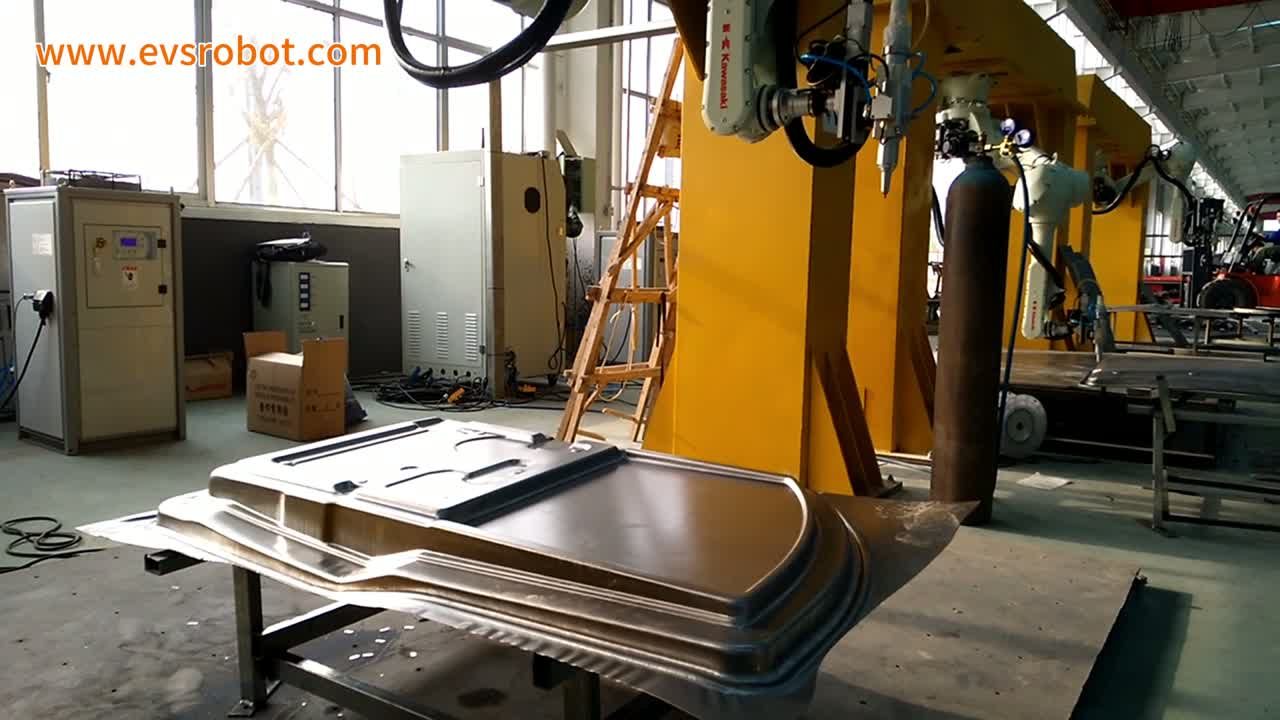
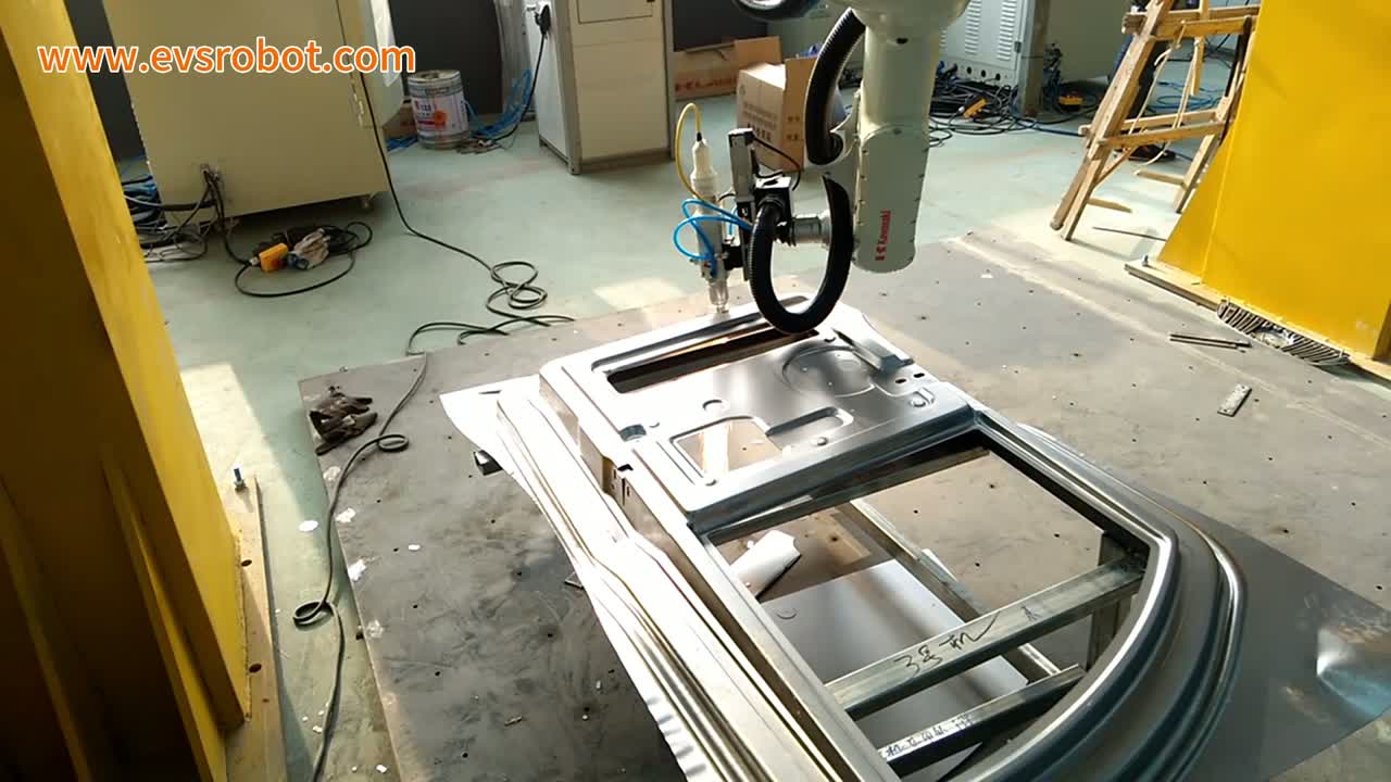
In short: A single robot arm reaches down from above to run a slim laser cutting head around a large stamped car door panel resting on a square-tube stand. The panel carries a window-sized opening, several rectangular cutouts, pressed grooves and a wavy lower flange, and the clearest machining trace in the pass is a burst of orange sparks at the panel’s lower edge that falls onto the steel plate below the stand. Three things carry a cell like this: how the panel is rested and referenced on the stand, how the head keeps pointing at the contour as it moves, and how the opening and the outer edge finish in one pass. Planning something similar? Send us your part drawing.
At a glance
| Part | Large stamped car door panel with a window-sized opening, rectangular cutouts, pressed grooves and a wavy lower flange |
| Process | Robotic laser trimming along the panel contour |
| Automation | One robot arm with a slim cutting head working over the panel |
| Part supply | Not shown — stacked thin sheets sit under and beside the stand |
| Locating | The panel rests on a square-tube stand with light wood pads; the locating method is not visible |
| Workholding | The panel sits on the stand; no clamps are visible |
| Operator role | No operator appears in the frames shown |
| Cell layout | One robot arm over a stand, in a workshop with yellow steel framing and a control cabinet |
The problem this cell addresses
A car door panel comes out of the press with a finished shape but an unfinished edge. The outer contour and the window opening still have to be trimmed, and the panel’s size and thin walls make that a harder job than it looks. Cutting the edge with a trim die ties each model to its own tooling — change the model and the die changes with it. Trimming by hand along the contour is slow, and keeping a long, curved edge straight by eye is a real struggle.
A robot arm with a laser cutting head can follow the contour instead of cutting it with a die, so a new trim die is no longer needed for each model — the path and the panel supports still have to be set up per model — and the edge is followed by machine motion rather than by hand. The footage shows one robot arm carrying a slim cutting head with a conical tip, tracing the panel’s contour and its window opening.
How the cell runs
- The panel waits on the stand. A large stamped panel rests on a dark square-tube stand lined with light wood, its window-sized opening facing up.
- The head approaches. The slim cutting head moves above the panel and eases down toward the surface, the whole panel and stand in frame.
- Sparks at the lower edge. At the panel’s lower edge the conical tip hugs the contour and a burst of orange sparks sprays down onto the steel plate under the stand.
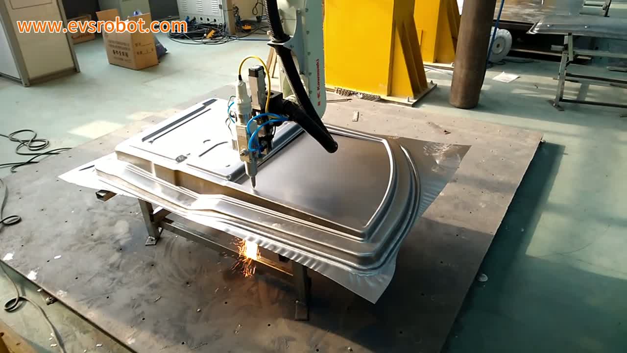
- It follows the contour. The head shifts along the panel’s edge, the tip always pointing down at the surface.
- It pauses at a groove. Mid-panel the tip stops beside a pressed groove, almost touching the surface.
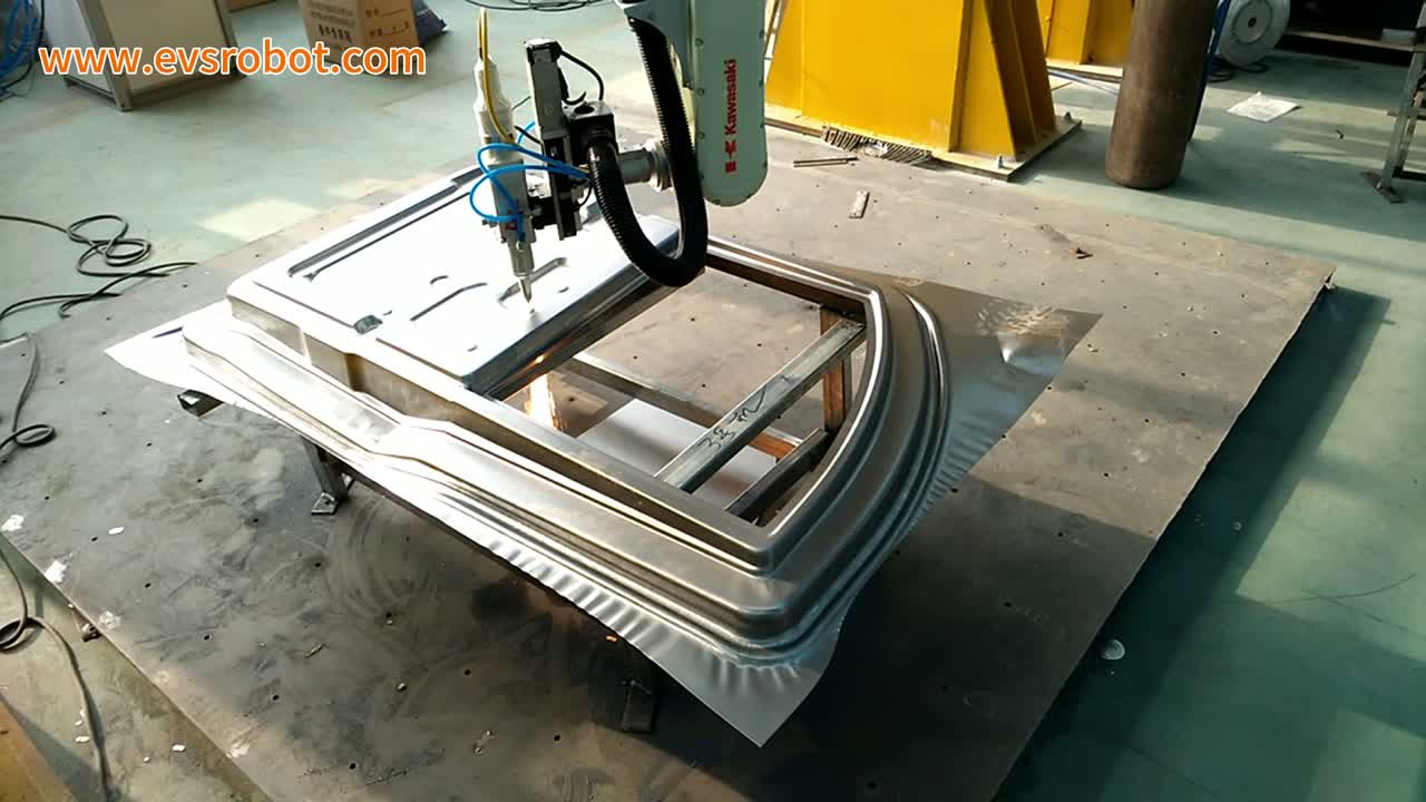
- It works around the opening. The head moves around the window opening, the black corrugated tube swinging with the wrist.
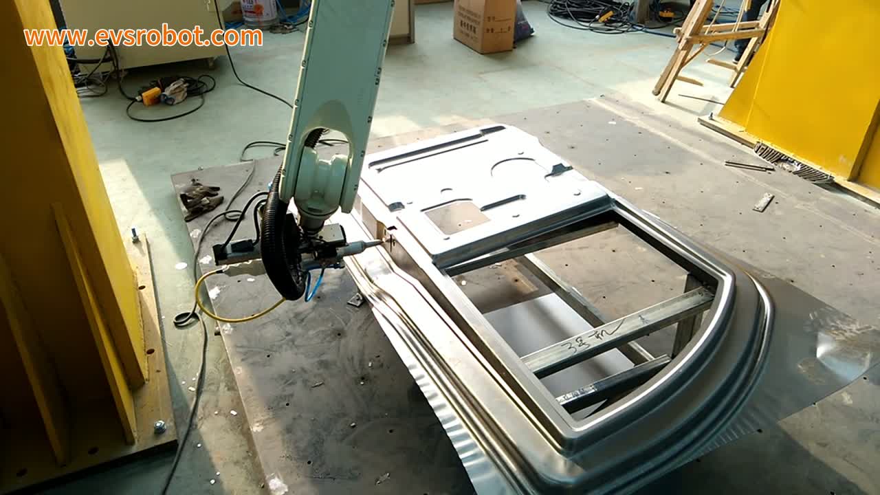
- It finishes the pass. The head pauses above the opening’s edge to finish, the panel’s wavy lower flange in view.
Three design decisions
1. Give the panel a repeatable rest
In the footage the panel rests on a square-tube stand lined with light wood, and more sheets sit stacked beside and under the stand. The stand and its pads have to present every panel the same way — the same rest faces, the same contact points — or the head traces one panel’s edge and the next panel’s edge sits a little off. Deciding the rest means naming the faces that carry the panel and making sure it does not shift while the head moves across it.
2. Keep the head pointing at the contour
The head in the footage is a slim body with a conical metal tip held down toward the panel, tracing the edge as it moves. A cell like this generally keeps the cutting head at a steady distance and angle to the surface along the whole path, so the cut lands on the contour instead of drifting off. The arm’s reach and the way it turns around the corners decide whether the head keeps that attitude through the pass.
3. Finish the opening and the outer edge in one pass
A door panel has both an outer contour and a window-sized opening. The layout worth having walks the head around both without re-referencing the panel in between, so the two edges are covered without stopping to re-locate the panel.
When this layout fits — and when to look closer
- Good fit: large stamped sheet-metal parts with a contour and openings to trim, panels that can rest on a stand the same way every cycle, and model changes where a die would otherwise have to change with each one.
- Evaluate further: panels that are hard to hold still without clamping, edges that need a different finish or angle than a straight pass can give, and any part where loading and unloading have to be folded into the same cell.
FAQ
Does the robot also load and unload the panel?
The footage only shows the trimming pass — the panel stays on the stand throughout, and how panels arrive and leave is not shown. A project decides loading and unloading separately from the cutting motion.
What decides the cycle for a cell like this?
The length of the path around the contour and the opening, how many corners the head has to turn, and how the arm moves between them. It is not a single number that this footage can give.
What should I send to get an estimate?
A drawing of the panel with the edges and the opening you need trimmed, the material and thickness, and your daily or annual volume. We come back with a layout and a cycle-time estimate.
Get a layout and cycle-time estimate
Send us:
- Panel drawing with the contour and opening you need trimmed
- Material and sheet thickness
- How the panel arrives and how it is held on the stand
- Daily or annual volume and shift pattern
- Photos or dimensions of the floor space
We will reply with a cell layout proposal and a cycle-time estimate.
Send your part drawing → or email sales@evsrobot.com
Footage filmed at a partner’s production site. Cycle time, output and other figures from that site are not public and are not given here.