
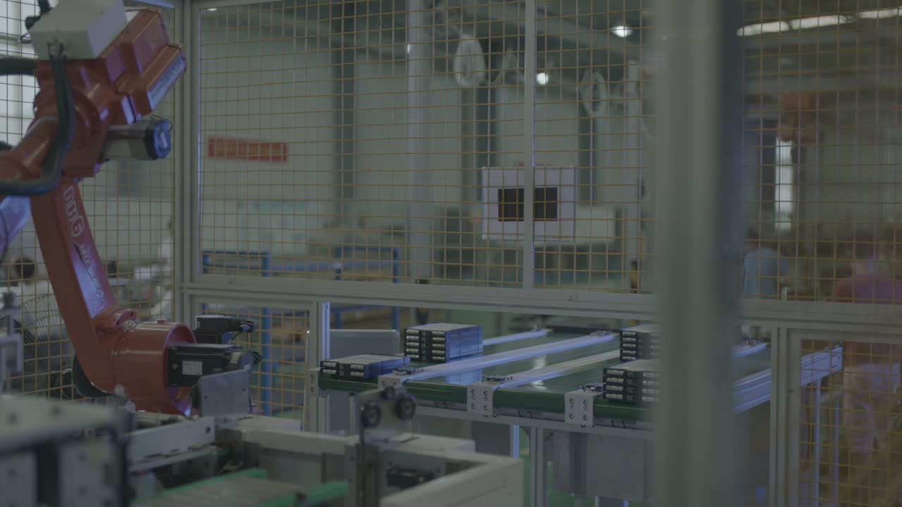
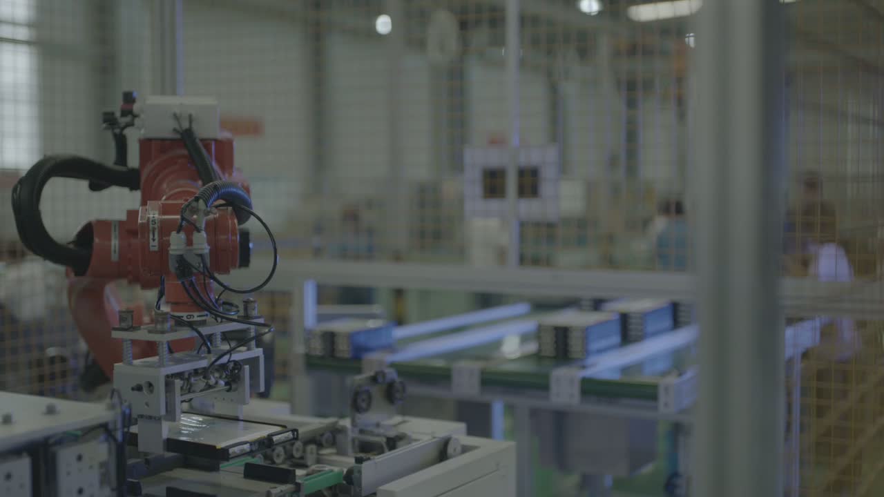
In short: This cell hands the moving of battery modules to one six-axis robot. The robot stands on a floor column inside a safety fence and cycles between a conveyor line and a station beside it: it stops over a row of dark rectangular modules, dips the tool down, lifts and turns, and brings the tool down at the station beside the conveyor; a light slide moves parts along the station on rollers. The same pose — arm up, dip down, back to the station — repeats through the footage. Three decisions carry a cell like this: how the trays and carriers locate, how the end-of-arm tool fits the grouped modules, and how the conveyor and the station share one robot’s time. Planning a similar line? Send us your part drawing.
At a glance
| Part | Dark, near-black rectangular modules, several to a light tray |
| Process | Material handling — module transfer from conveyor to station |
| Automation | One six-axis robot on a floor column, inside a safety fence |
| Part supply | Rows of grouped modules on a flat-belt conveyor |
| End-of-arm tool | A light mounting plate with black square pieces below, air hoses and cables |
| Station | A light slide carries modules along the line, parts resting on rollers |
| Operator role | Stays outside the fence; the robot does the moving |
| Cell layout | One robot between a conveyor line and a station, fenced |
The problem this cell addresses
Battery modules move back and forth between a conveyor and a station at a tight pace, and someone has to keep that flow going. Done by hand, the work is tiring, easy to knock modules against each other, and hard to staff — the kind of repetitive transfer a person does not stay at for long.
In this cell the robot does the moving. It stops over the row of dark modules, dips the tool down, and lifts and turns between the conveyor and the station, while the workers stay outside the fence the whole time. What keeps a loop like this steady is the setup around the robot — where each tray stops, how the tool meets the group, and how the conveyor and the station share the cycle.
How the cell runs
- Wait over the parts. The wrist holds the end-of-arm tool above the conveyor, plate facing down, over the row of dark rectangular modules.
-
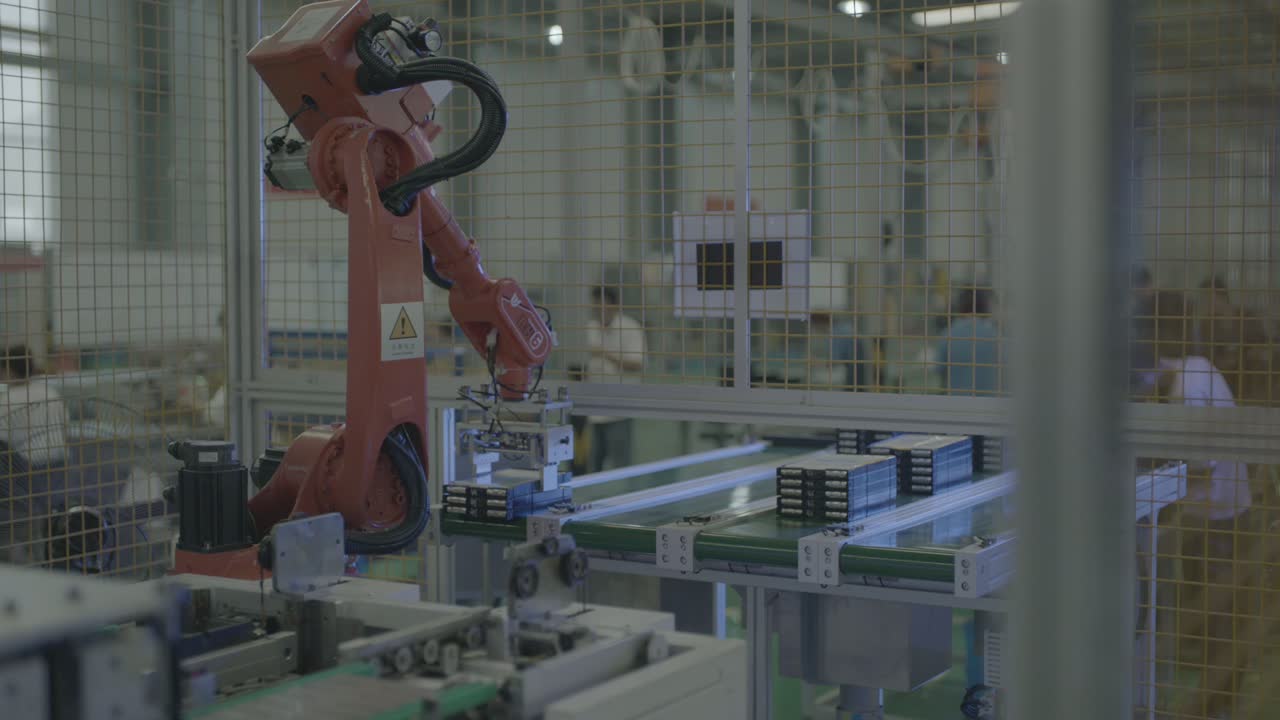
Dip to the parts. The wrist drops and the tool comes down over the group of modules on the conveyor.
-
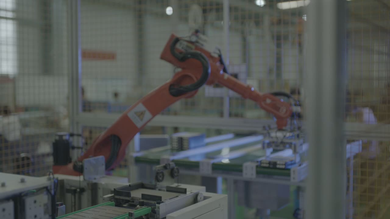
Lift and turn. The arm lifts, swings wide, and moves the tool from the conveyor to the station beside it.
-
At the station. A light slide carries the modules along the line with the parts resting on rollers.
-
Raise above the fence. When the arm lifts, the tool rises near the top rail of the fence before the next move.
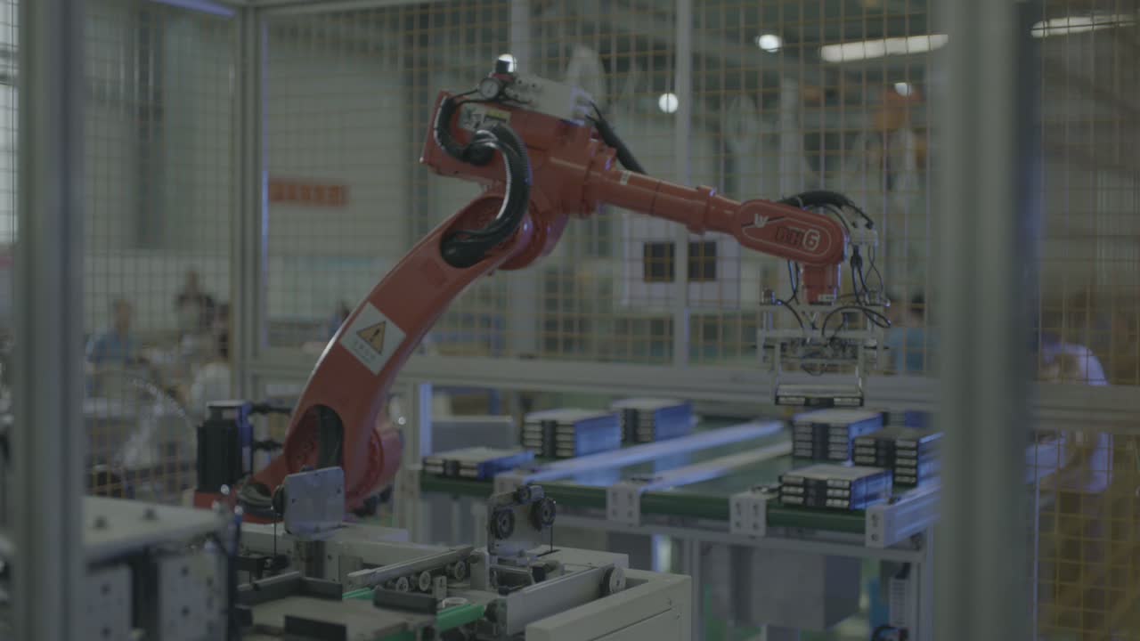
- Repeat. The same pose — arm up, dip down, back to the station — repeats through the footage, one continuous loop.
The robot stays inside the fence the whole time; the workers in the background stay outside it.
Three design decisions
1. Let the tray set where the tool meets the group
In this cell the modules sit several to a tray and line up in a row, and the tool comes down over the group from above. A tray that stops at a known spot lets the tool meet the group the same way every cycle.
A layout like this stands or falls on the tray: it has to hold the group, give the tool a face it can reach, and let the tool come down without pushing the modules out of place.
2. Match the tool to the grouped modules
The tool here is a light mounting plate with black square pieces below it, with air hoses and cables running down the arm. Whatever the holding principle, the shape is the point: the tool must meet the module’s top face and the tray’s spacing.
The question is whether the tool can come down over every group the same way and come away without the modules shifting.
3. Share the cycle between the conveyor and the station
The arm’s pose repeats — arm up, dip down, back to the station — and a light slide moves parts along the station on rollers. In a balanced loop the conveyor presents the next group while the robot is at the station.
Balance is what to watch: if the conveyor and the station are ready at about the same time, the robot’s moves fit between them without either side waiting; if one side runs much longer, that side sets the pace and the other mostly waits.
When this layout fits — and when to look closer
- Good fit: grouped modules that move between a conveyor and a station in a steady rhythm, modules that sit on a tray or carrier so the tool meets them the same way each time, and a cell where a fence can keep people out of the robot’s path.
- Evaluate further: modules that change shape or spacing often, so the tool has to change with them; trays or carriers that do not stop at a repeatable point; and cases where the conveyor and the station fall out of step so the robot ends up waiting.
FAQ
Does the robot move the modules one at a time or several at once?
The modules sit several to a tray, and the tool meets the group from above. Whether it moves one module or the whole group is settled by the tray design and the tool — both are worked out from the part drawing.
What decides how fast this cell runs?
The rhythm of the conveyor and the station, and how the robot’s moves fit between them. A cycle-time estimate comes from the part drawing, the tray layout and the daily volume, so send those and we can work it out.
Could one robot serve more than one station?
In principle, yes, if the extra move stays short and the timing still lines up. Each added position lengthens the robot’s round trip, so the question is whether the robot can get through every move before the next group is ready.
Get a layout and cycle-time estimate
Send us:
- Part drawing with the faces you need touched and the tray or carrier layout
- Part material, size and weight
- Number of part types and how often you change over
- Daily volume and shift pattern
- Photos or dimensions of the floor space and the existing conveyors
We will reply with a layout proposal and a cycle-time estimate.
Send your part drawing → or email sales@evsrobot.com
Footage filmed at a partner’s production site. Cycle time and other figures from that site are not public and are not given here.