
Robotic welding of a large frame should be laid out from its most restricted required joint, because that joint can dictate robot position, fixture height, clamp placement and the route to every joint that follows. The footage shows one orange robot welding separated joints on a fixed tubular or beam frame. It supports an access-led concept review, while the required weld extent and production result still need project evidence. Ask EVST to review your application →
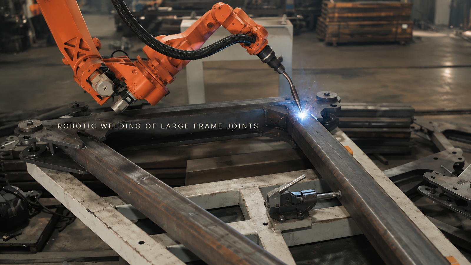
Let the hardest joint define the first layout
The open side of a frame can make one arc look straightforward while a tube, clamp or fixture post blocks the next joint. Robot reach alone does not settle the question. The torch neck, nozzle, cable package and retreat direction all need clearance at the required working angle.
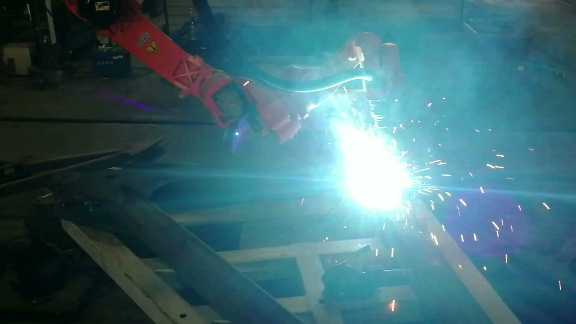
At 00:40.33, the close view confirms an active arc at one joint on the fixed frame.
Start with the most obstructed joint on the drawing. Sweep the complete torch package into its start position, through its required path and back out again. Then place the fixture around that envelope. A datum or clamp that improves location but occupies the only usable approach changes the automation concept.
Long members also need enough support to limit sag and movement. That support must control the frame without taking away the access just established. The useful early model therefore combines the actual frame, proposed supports and clamps, torch geometry, cable envelope and measured incoming variation.
Review every joint as access, location and route
The wide view shows why the whole assembly matters: the robot, frame and steel fixture share the same constrained volume.
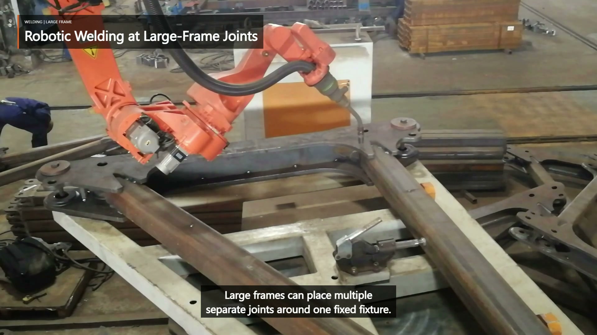
At 00:03.50, the wide view keeps the robot, torch, fixed frame and steel fixture in the same scene.
| Joint review question | Evidence to bring | Concept consequence |
|---|---|---|
| Can the full torch package approach and retreat? | Joint angle, required torch angle, start/end region and nearby members | Robot mounting, frame presentation or automated scope may change |
| Does the fixture return the joint predictably? | Stable datums, clamp positions, tack condition and measured gap range | Path repeatability depends on part presentation, not programming alone |
| Can the robot move from the previous joint without crossing an obstruction? | Fixture envelope, cable sweep and non-arc route | Joint order and intermediate poses become part of the layout |
| Can the required area still be inspected? | Drawing, weld specification and inspection access | Layout must reserve a usable acceptance view |
This connects each seam requirement to the physical change it may force elsewhere in the cell.
Sequence can send the layout back for revision
Separated arcs in the footage are linked by arc-off repositioning. A proposed order must preserve access after earlier welds, avoid trapping the cable behind the frame, and account for assembly movement as welding progresses. Heat and distortion are project-specific, so the sequence should be tested against the drawing and weld requirements rather than inferred from a partial video.
If a later joint loses clearance, a start or stop cannot be placed in an allowed region, or measured frame movement moves a joint outside the planned path, the answer may be a fixture change or another frame presentation—not finer programming. This feedback is why route planning belongs in the layout study.
Bring the difficult joint to the concept review
A useful review starts with the frame drawing and joint list, weld symbols and acceptance criteria, incoming member tolerances and tack condition, proposed datums and fixture envelope, and representative parts. Mark the most obstructed joint and the greatest expected variation. The first trial should prove access, repeatable fit-up and inspection at those conditions before output is estimated.
Send these inputs for an EVST concept review → or email sales@evsrobot.com.
The footage records visible multi-joint welding; final tooling, controls, safeguarding and production acceptance depend on project validation.