
By EVST toimetus · Arvustanud EVST toimetus · Viimati uuendatud 19. oktoobril 2026
Meetod: piiratud juhtumianalüüs video abil ja inseneriviited · Toimetamise poliitika · Paranduspoliitika · Tingimused
A robot transfer between a supply station and a pallet area depends on three connected handoffs: present the part in a repeatable pickup condition, support and retain it through the route, then place it within the receiving area with a clear tool exit. In the case video, an orange industrial robot repeatedly moves its suction-cup end effector between a rear station and a wooden pallet at the front, approaching different positions near the pallet.
Request a robot transfer concept and cycle-study review with the part drawing, daily output target, incoming presentation and pallet-area layout.
Follow the route between the two handoff zones
The rear station and the wooden pallet define the two ends of the visible route. Between them, the robot changes position and end-effector orientation. This repeated motion gives the project team a practical starting point for defining pickup, retained transfer, placement and withdrawal as one continuous sequence.
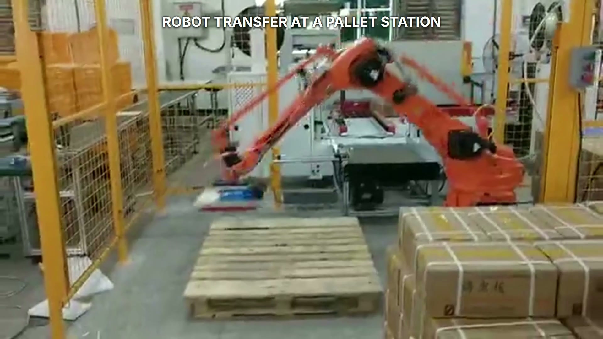
Route overview: the robot connects the rear supply station with the wooden pallet receiving area.
Define a repeatable pickup condition
Vacuum pickup starts with the surface presented to the cups. The project must identify available contact zones, holes or features to avoid, expected flatness, surface condition and the variation in incoming position. The supply station should support the part without blocking the selected cup pattern or the robot’s approach and withdrawal.
Record the part datum and the state that permits pickup. If multiple parts or variants enter the same station, define how the control system identifies the correct presentation and program. Select sensing only after these conditions are clear.
Check the complete vacuum load path
A suction cup creates a local holding point, but the whole part still reacts to acceleration, orientation changes and external disturbance. Tool design should consider the cup pattern, compliant elements, manifold arrangement, vacuum generation, loss monitoring and the stiffness of the tool structure. The part drawing, mass, surface and permitted contact areas are necessary inputs.
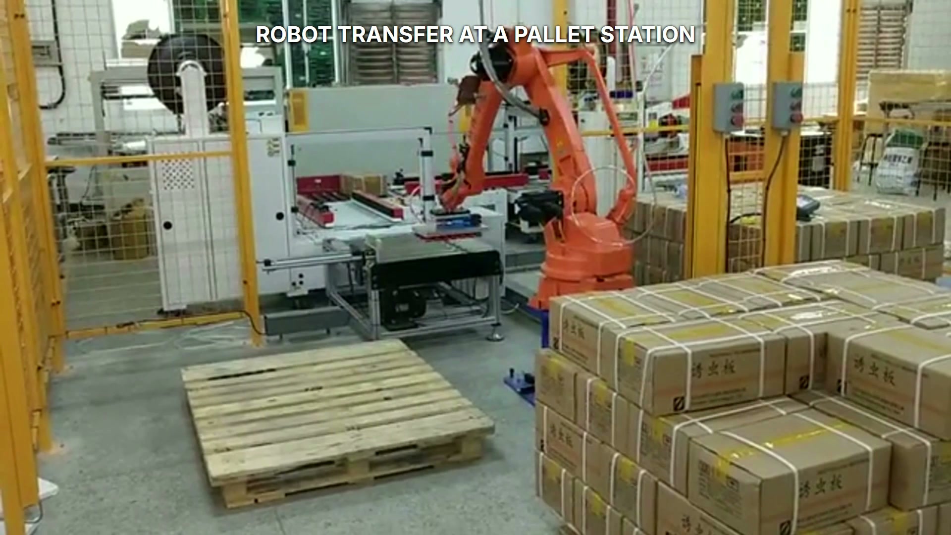
Rear-station view: the robot positions its suction-cup end effector above the station.
Validate the complete tool-and-part envelope rather than the robot tool-center point alone. Include cups, brackets, hoses, fittings and the largest expected part position. Review clearance at the rear station, along the connecting motion and above the receiving area.
Match engineering decisions to project inputs
| Inseneri otsus | Nõutav projekti sisend | Vastuvõtukontroll |
|---|---|---|
| Pickup presentation | Part drawing, incoming position, available datum and surface condition | The tool reaches the approved contact zones and withdraws without disturbing the supply station. |
| Vacuum tooling | Part mass, stiffness, contact restrictions, cup data and vacuum architecture | Representative parts remain supported through every validated orientation and motion. |
| Transfer route | Robot model, mounting position, tool geometry, hoses and surrounding equipment | The full robot, tool and part envelope clears both stations and the connecting route. |
| Pallet receiving area | Pallet geometry, placement datum, allowed area and access direction | The part reaches the defined receiving area and the tool withdraws without contact. |
| Sequence and signals | Part available, grip confirmation, receiving-area permission and release confirmation | Each transition begins from an identified and confirmed state. |
| Tootmiseesmärk | Daily output, product mix, replenishment plan and permitted waits | Esinduslikus uuringus mõõdetakse kogu järjestust kokkulepitud tingimustel. |
| Recovery and access | Stop states, access tasks and site safety requirements | The team can identify part location and execute a controlled recovery. |
This table separates application facts from engineering selections. It also gives buyers a common basis for comparing tool concepts, robot locations and station layouts.
Define the pallet handoff and tool exit
The receiving area needs a datum or permitted placement zone, an approach direction and enough space for the vacuum tool to release and withdraw. Define how the part remains supported after release and how the system confirms that the receiving area is ready for the next transfer.
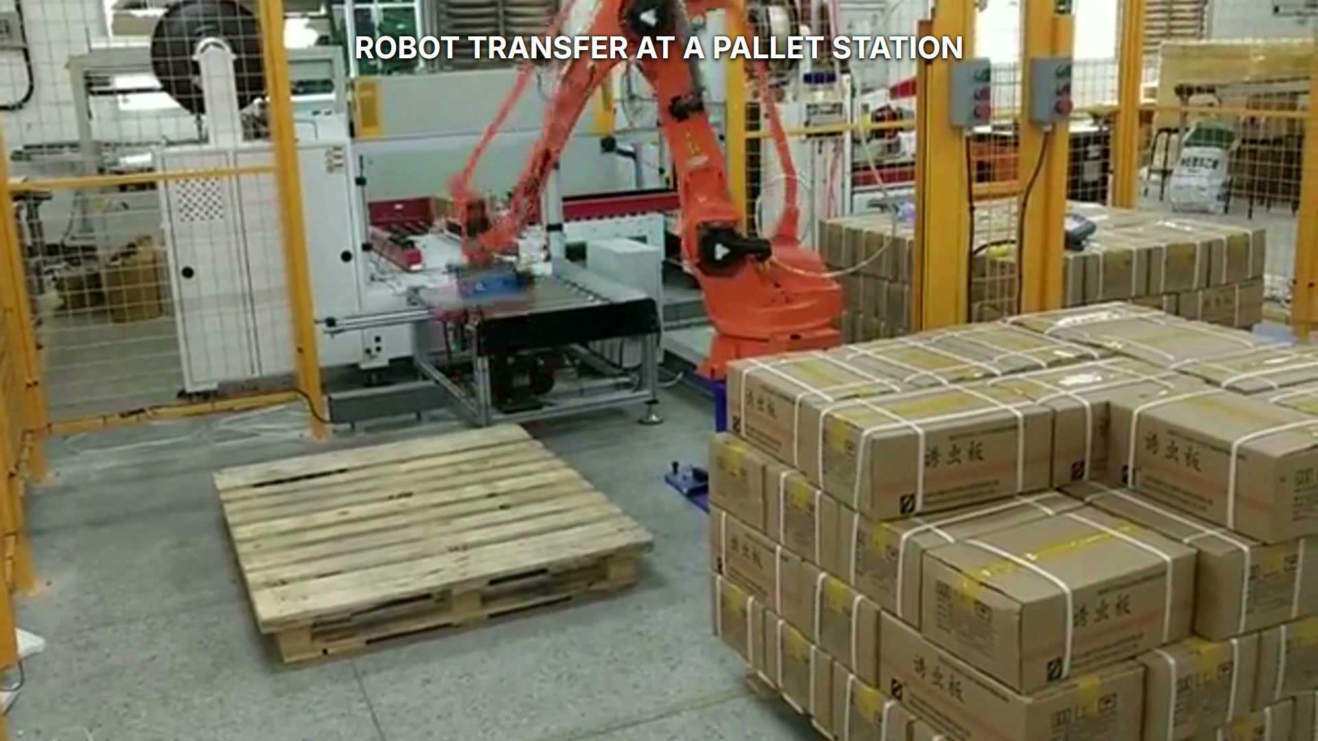
Pallet-area view: the robot approaches the wooden pallet with a changed end-effector orientation.
Include pallet position variation, replacement or replenishment tasks and access for recovery in the layout review. If the real project requires a pattern, layer or separator sequence, those requirements must be supplied as project inputs and verified during trials.
Loo jada lubade ja kinnituste põhjal
A useful control sequence can be written in six conditions:
- Confirm the correct part is available at the supply station.
- Enter the pickup zone and engage the vacuum tool at approved contact areas.
- Confirm the project’s required retained-part condition before withdrawal.
- Confirm that the receiving area is ready before entering it.
- Present the part at the defined placement datum or area, release and withdraw.
- Confirm the receiving state before permitting the next station action or transfer.
The actual sensors, thresholds and control architecture should be selected for the part, tool and site. A representative trial should include normal transfer, missing-part conditions, interrupted motion and controlled recovery.
Plan recovery around the physical part state
After a stop, the part may remain at the supply station, be held by the vacuum tool or rest in the pallet area. Recovery starts by identifying that physical state and the permission status of both zones. A defined recovery route should prevent a second pickup, an unintended release or entry into an occupied area.
OSHA-d tööstusrobotite süsteemide tehniline juhend describes robot applications as integrated systems that can include end effectors, worktables, clamps, process equipment and other machines. The robootikastandardite ülevaade provides a starting point for U.S. integration, guarding and hazardous-energy references. Qualified personnel must establish the applicable path for the actual country, equipment and tasks.
Measure the complete application sequence
Cycle assessment should use defined start and end states and include part presentation, pickup, grip confirmation, transfer, placement, release, withdrawal and station waits. Test representative parts and the expected station variation. Record any replenishment, changeover and recovery steps that affect the planned production day.
Acceptance should confirm pickup access, retained transfer, route clearance, receiving-area placement, tool exit, controlled stops and recovery. Any placement tolerance or surface acceptance requirement must come from the project specification and be measured under agreed conditions.
To discuss a pallet-station robot transfer project, send the part drawing and daily output target to EVST, together with the supply and receiving-area layout. The robot palletizing application page offers additional project-scoping context.
Küsimused, mida ostjad sageli küsivad
Milliseid andmeid peaks ostja kõigepealt ette valmistama?
Start with the part drawing, mass, surface condition, permitted suction areas, incoming presentation, pallet-area geometry and daily output. Add product variants and replenishment tasks so tooling and layout can be reviewed together.
How should a vacuum tool be evaluated?
Review the cup pattern, compliance, vacuum generation, monitoring, hose routing and tool stiffness against representative parts. Validate every required orientation and motion under agreed trial conditions.
What defines a practical receiving area?
Provide a placement datum or allowed zone, pallet position variation, approach direction, support after release and clear tool withdrawal. Include pallet access and replacement tasks in the layout.
Millal peaks tsükliaega mõõtma?
Measure after both handoff zones, the complete route, control permissions and recovery states work with representative parts. Include real station waits and replenishment activities defined by the project.
Footage boundary: the video shows an orange industrial robot repeatedly moving its suction-cup end effector between a rear station and a front wooden pallet and approaching different pallet positions; it does not establish a completed pickup or stack, part identity, stacking pattern, layer count, payload, cycle time, placement accuracy, sensing method, production benefit, customer identity or installed safeguarding.