
Collaborative robot vision inspection works when each required feature is tied to a stable part reference, a controlled view and lighting condition, an explicit decision rule, and a recoverable recheck path. Robot motion can place a sensor around a complex housing, but movement alone does not establish image quality or detection capability. Validate representative parts, known conditions, occlusion cases, uncertainty, and reject handling before making any coverage or quality claim.
Key takeaways
- Start with a feature-and-condition matrix rather than a list of camera poses.
- Define how the part coordinate system relates to fixture, robot, sensor, and image.
- Treat lighting, exposure, surface condition, focus, and field of view as one imaging setup.
- Record occluded, low-confidence, missing-image, and communication cases instead of silently classifying them.
- Compare fixed cameras, robot-carried cameras, and manual verification with the same acceptance and recheck rules.
What the selected evidence shows—and what it does not
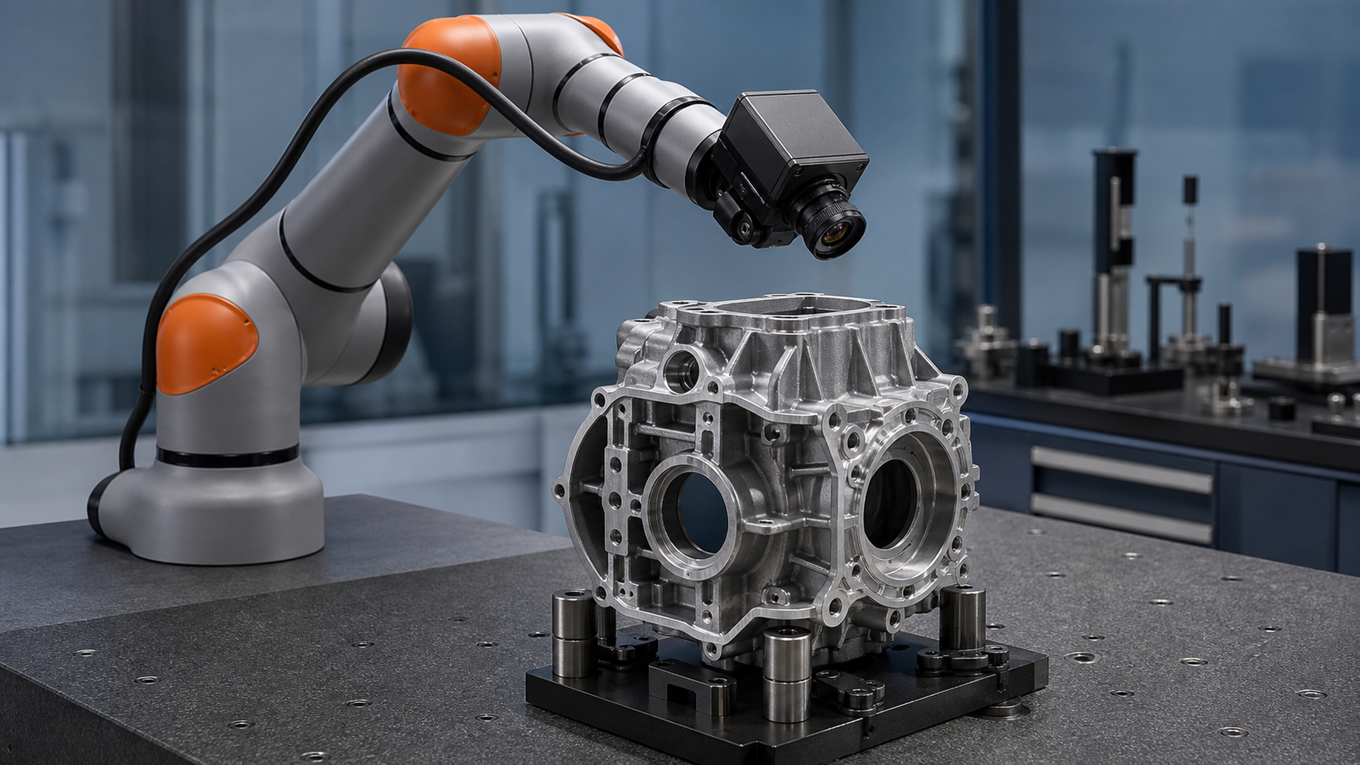
The selected sequence shows a collaborative robot form factor moving around a complex metal housing and presenting a device toward several surfaces. The changing viewpoints support discussion of robot-carried sensing, feature access, view planning, possible occlusion, and recheck routing.
The footage does not identify the sensor type, whether the device captures two-dimensional or three-dimensional data, lens, illumination, exposure, feature list, reference method, calibration, measurement uncertainty, algorithm, training data, defect set, inspection coverage, accuracy, false-call behavior, cycle time, traceability system, acceptance result, or production deployment. No claim of “100% inspection” or a numerical detection result can be derived from it.
That boundary changes the design conversation. The question is not “Can the arm look around the housing?” It is “Can every required condition be observed with controlled evidence and routed to a defined pass, fail, or recheck state?”
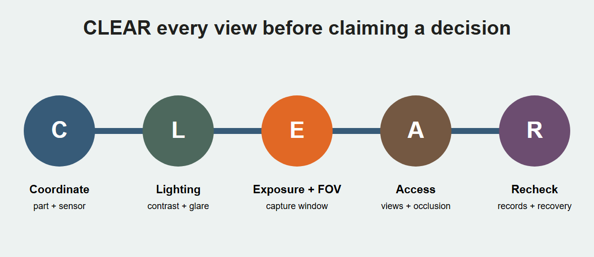
A collaborative robot vision inspection method: CLEAR
EVST uses CLEAR to structure an early inspection review:
- C — Coordinate reference: part datum, fixture reference, robot frame, sensor frame, and feature identity.
- L — Lighting: direction, spectrum or source selection, glare control, ambient isolation, and condition monitoring.
- E — Exposure and field of view: working distance, focus, feature size, image region, motion state, and capture trigger.
- A — Access and occlusion: tool clearance, camera pose, blocked surfaces, cables, and collision envelope.
- R — Recheck and records: confidence or validity states, retry rules, manual disposition, image retention, and change control.
CLEAR does not select a camera or guarantee a result. It reveals the project evidence needed to compare architectures and design trials.
1. Translate product requirements into a feature matrix
List every feature or condition to be checked and link it to the drawing, specification, control plan, or agreed product requirement. Describe what constitutes an acceptable observation without assuming a vision method. Examples might include presence, orientation, surface condition, label or code readability, connector state, or a dimension—but each needs its own scope and evidence.
2. Establish the coordinate and identity chain
A robot-carried sensor needs to know which part is present and where the target feature is relative to the sensor. Define part location in the fixture, fixture reference to the robot, robot tool or sensor frame, and the image region used for the decision. State how product variant and program are selected and confirmed.
Robot pose repeatability is only one contributor. Fixture variation, part seating, sensor mounting, calibration, lens behavior, thermal conditions, and feature geometry can shift what appears in the image. ISO 9283 provides methods for evaluating manipulating industrial robot performance; it does not establish measurement performance for a complete vision-inspection cell.
Plan reference checks that can reveal a changed relationship. These may include a known artifact, fixture target, fiducial, image-health feature, or another project-specific method. Define when a reference check is required—after service, collision, sensor adjustment, software change, or a failed health check—and what happens when it is outside its allowed condition.
3. Design lighting before optimizing decision logic
Machine-vision images are created by the interaction of light, surface, geometry, lens, and sensor. A feature visible to a person under one shop light may disappear when the part is oily, rotated, more reflective, or exposed to changing ambient light.
The Association for Advancing Automation’s machine-vision lighting guidance explains how lighting geometry and technique affect contrast and feature visibility. For a robot-carried system, lighting may be mounted with the sensor, fixed in the station, or combined. Each arrangement changes shadow, glare, cable load, collision envelope, and repeatability of the optical condition.
4. Define the capture window
For each feature, specify working distance, field of view, desired image region, focus condition, camera orientation, lighting state, exposure or equivalent acquisition settings, robot state, and trigger confirmation. Decide whether the robot must be stationary, may settle at a pose, or can capture during motion only if that method is validated.
A wider field of view can show more context but may reduce the useful image detail available to a small feature. A close view can improve feature visibility while shrinking tolerance to part location or robot position. Those tradeoffs must be tested with the chosen sensor and actual parts; footage cannot resolve them.
Add image-validity checks. A missing trigger, saturated frame, blur, blocked lens, lost lighting, wrong variant, or incomplete transfer should not be treated as an inspected good part. Create an explicit “no valid decision” state.
5. Plan access and occlusion as a view set
Complex housings create cavities, ribs, flanges, connectors, and reflective surfaces that block or distort a view. Build a view set for the feature matrix. One pose may cover several compatible features; another feature may require two views to manage occlusion or orientation.
Model the sensor housing, lens guard, lighting, mount, wrist, cable, and robot body. Include approach and retreat, not only the capture pose. Check fixtures, guards, conveyors, neighboring tools, and the part at tolerance extremes. Protect the sensor from collision and from process contamination without blocking its optical path.
When a feature cannot be observed reliably, document the gap. Options include changing fixture orientation, adding a fixed camera, adding controlled lighting, modifying the part presentation, using a different sensing method, or routing that feature to manual verification. Hiding the gap behind a general “multi-angle inspection” label creates an unsupported coverage claim.
6. Build a representative image and condition set
Trials need identified parts that represent normal production variation and known conditions relevant to the feature matrix. Include acceptable and unacceptable examples where practical and permitted, along with borderline or ambiguous states that should trigger recheck or manual disposition.
NIST’s manufacturing and robotics measurement work emphasizes performance assessment and measurement science rather than conclusions from demonstrations. The same principle applies here: define the measurand or decision, reference condition, uncertainty contributors, test procedure, and reporting boundary.
7. Choose metrics that match the decision risk
Do not compress performance into one unspecified “accuracy” number. For a classification task, teams may need confusion categories, false acceptance, false rejection, invalid-image rate, and behavior by defect or condition class. For a measurement task, they may need bias, repeatability, reproducibility, uncertainty, range, resolution, and traceability appropriate to the requirement.
The exact metrics and sample design depend on the application and consequence of error. State the population represented by the test parts and the conditions not covered. A result on a limited sample does not justify a universal detection or coverage statement.
Link every metric to a disposition. A low-confidence or out-of-window result may route to a second automated view, a recapture after cleaning, manual verification, rejection, or stop. Decide that route before production so the system does not improvise.
8. Design recheck and fault recovery
Define what triggers one recapture at the same pose, a new view, part repositioning, lens inspection, fixture reseating, or manual review. Limit automatic retries so a persistent bad condition does not consume time or overwrite the original evidence.
Create controlled responses for wrong part, part not seated, reference check failure, robot-position fault, sensor communication loss, lighting fault, missing image, storage fault, low-confidence result, ambiguous result, and inspection reject. Preserve the original result and part identity through recovery.
9. Compare architectures with the same condition matrix
| Architecture | Useful when | Main advantage to test | Main limitation to test |
|---|---|---|---|
| Fixed camera set | Features arrive in stable locations and views | Simple capture timing and no robot motion between views | Multiple cameras or part reorientation may be needed; occlusion can be fixed |
| Robot-carried camera | Features are distributed around a complex part | Flexible viewpoints and potential sensor sharing | More pose, cable, collision, capture-time, and calibration dependencies |
| Manual verification | Conditions need human interpretation or low-volume flexibility | Adaptable viewing and contextual judgment | Ergonomics, consistency, documentation, and staffing must be managed |
Use one feature matrix, representative condition set, disposition logic, and evidence-retention plan for all three. Compare complete accepted decisions, including handling, capture, processing, recheck, manual review, changeover, maintenance, and recovery.
Hybrid architectures are often reasonable. Fixed cameras can handle stable high-frequency views, a robot-carried sensor can reach distributed surfaces, and manual verification can resolve explicitly defined ambiguous cases. The architecture should follow evidence needs rather than a desire to automate every view with one device.
10. Commission from image validity to production states
Begin with part identity, fixture reference, sensor health, lighting, and capture confirmation. Prove one feature under normal and challenging acceptable conditions, then evaluate known unacceptable and invalid-image states. Expand across the feature matrix and product variants.
Run the complete part sequence, including transfer, view order, decision aggregation, recheck, reject routing, and data recording. Test changeover, sensor or light service, changed surface condition, part not seated, wrong program, communication loss, blocked view, and interrupted cycle.
Release only the features, variants, conditions, and configuration actually evaluated. Keep a change-control list for sensor mount, lens, lighting, enclosure, fixture, robot frame, software, thresholds, and product changes that can invalidate earlier evidence.
Citable statements
A vision decision needs a reference chain from part and fixture through robot and sensor to the image; robot pose alone is not a measurement result. Source basis: ISO 9283 defines robot-performance evaluation, while NIST frames manufacturing automation around performance assessment and measurement science. Boundary: the project must define the complete cell reference and uncertainty method.
Lighting and view validity are inspection inputs: a saturated, blurred, blocked, missing, or wrong-variant image is not a valid inspected result. Source basis: the Association for Advancing Automation explains how lighting geometry affects contrast and feature visibility; the article’s CLEAR review maps that principle to capture validity. Boundary: thresholds and health checks require the selected equipment and representative parts.
A robot-carried camera is justified by controlled access to distributed or occluded features, not by motion alone. Source basis: the observed source sequence shows multiple viewpoints around a complex housing. Boundary: it does not establish feature coverage, sensor type, accuracy, or detection performance.
An uncertain vision result needs an explicit recheck, manual-verification, reject, or stop route rather than an automatic pass. Source basis: the CLEAR method separates recheck and records from view acquisition. Boundary: the route and decision risk remain project-specific.
Project input checklist
- Feature-and-condition matrix with source requirements and dispositions.
- Part variants, fixture and datum, handling state, and expected surface variation.
- Candidate sensor, lens, lighting, mount, cable, protective hardware, and interfaces.
- Required views, working distances, fields of view, obstacles, and access paths.
- Representative normal, unacceptable, borderline, and invalid-image conditions.
- Metrics, reference methods, sampling plan, acceptance rules, and limits.
- Recheck, manual review, reject handling, image retention, fault recovery, and change control.
The included input sheet can be populated before camera trials to distinguish requirements, assumptions, and verified evidence.
Frequently asked questions
Does the footage prove that a three-dimensional camera is used?
No. It shows a robot presenting a device toward several surfaces. The sensor type and data method are not established.
Can one wide image replace several close views?
Sometimes, but only if every required feature retains adequate visibility and decision evidence under representative conditions. Field of view, feature detail, glare, occlusion, and part variation must be tested.
What should happen when the image is unclear?
Route it to a defined invalid or uncertain state. The cell may recapture, change the view, request cleaning, send the part for manual verification, reject, or stop according to the agreed risk and process plan.
How should a vision-inspection claim be written?
Name the feature, part population, conditions, method, decision rule, evaluation evidence, and known limits. Avoid broad accuracy, defect-rate, or total-coverage language without that support.
When is manual verification still useful?
When conditions are infrequent, ambiguous, changing, or not yet supported by sufficient automated evidence. Manual review should still have instructions, ergonomics, records, and disposition rules.
Related resources
- Industrial automation line integration
- Robotic cell components and integration guide
- Automation solutions overview
- 3D-vision inspection cell application overview
Sources
- Association for Advancing Automation: Machine Vision and Lighting
- NIST Robotics and Manufacturing Automation
- ISO 9283:1998 — Manipulating industrial robots, performance criteria and related test methods
- ISO 10218-2:2025 — Industrial robot applications and robot cells
Who prepared this guide, how, and why
- Author entity: EVST Editorial Team, the same organization-level author used in the article byline and structured data. No individual employee credential is asserted.
- First-party observation: The team reviewed the selected multi-angle source sequence and recorded only the visible robot, housing, device presentation, and changing viewpoints; sensor type, algorithm, coverage, accuracy, detection, and production outcomes remained excluded.
- How: The team applied the CLEAR reference, lighting, capture, access, and recheck model; compared fixed, robot-carried, and manual architectures; and checked each technical statement against the evidence ledger and listed machine-vision, robot-performance, and measurement sources.
- Why: The guide helps inspection teams connect every view to a controlled reference, lighting condition, decision rule, recheck route, evidence record, and change-control trigger before equipment selection.
- Transparency: Editorial method · Corrections and updates · Privacy · Contact · Terms of use
Build the feature matrix before the camera trial
Send EVST the product variants, feature-and-condition matrix, fixture and datum, surface variation, required views, candidate sensing package, decision consequences, representative parts, recheck rules, and data-retention needs. We can organize them into a view-and-evidence trial plan; final sensing technology, capability, and acceptance remain subject to project-specific evaluation.