
Robot linear axis safety starts by treating the robot, carriage, tooling, services, fixtures, and neighboring machines as one application. The risk assessment must cover every permitted carriage position and every lifecycle task—not only the automatic cycle. Define limits, map people and motion, reduce risk by design before adding safeguards, specify safety functions from the remaining hazards, and validate normal, fault, and recovery states.
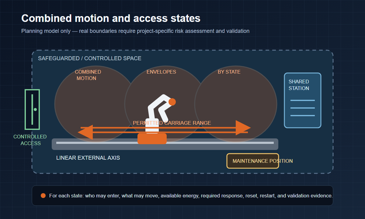
The diagram is a planning model, not a prescribed guard layout. Real boundaries depend on the application risk assessment, stopping behavior, access needs, and applicable requirements.
Key takeaways
- Assess the combined moving system across every permitted state, including non-routine work.
- Define hazards before selecting safeguards or safety-related controls.
- Derive safety functions from the project risk assessment, not an unrelated cell.
- Validate access, faults, reset, restart, and recovery with traceable evidence.
What the local evidence can support
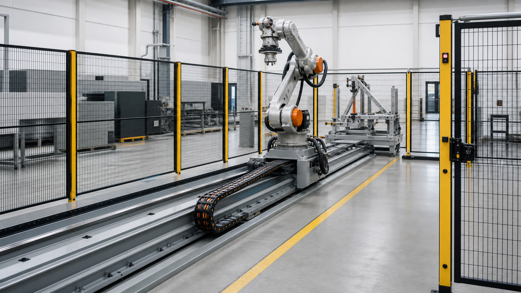
The two selected source sequences show an industrial robot mounted on a carriage that changes the robot base position along a floor-level rail. That visible movement is enough to illustrate why the motion envelope cannot be assessed from one fixed pedestal position.
The footage does not establish a safeguarded boundary, stopping performance, safety-rated function, safe distance, rail performance, or conformity. It cannot prove that the shown installation is safe or production-ready. This article therefore explains what a project team must determine and validate without prescribing a universal distance, performance level, or circuit.
1. Define robot linear axis safety limits
Risk assessment begins with limits, not with a guard catalog. Define the intended application, products, tools, operating modes, people, expected skills, environmental conditions, and lifecycle phases. Include the full carriage travel permitted by the controller, not only the positions used in the first production program.
Create a state list for production, setup, teaching, calibration, cleaning, maintenance, fault removal, power restoration, reference recovery, software changes, and decommissioning. For each state, record:
- the carriage position or permitted range;
- the robot pose and tool condition;
- other machines or fixtures that can move;
- available electrical, pneumatic, hydraulic, process, or stored energy;
- people who may enter and the task they perform;
- the command or event that can initiate movement; and
- the safe method for leaving the state.
ISO 12100 describes a lifecycle method for identifying hazards, estimating and evaluating risks, reducing risk, documenting decisions, and verifying the result. ISO 10218-2:2025 applies robot-cell integration requirements across design, commissioning, operation, maintenance, decommissioning, and disposal. These scopes matter because an external axis can change where hazardous motion exists during every one of those phases.
2. Map hazards across the combined motion
A linear axis makes the robot base position variable. The hazard review therefore needs a combined envelope for the carriage, robot links, end effector, workpiece, dress pack, energy chain, and process services.
Use scenarios rather than a generic checklist. A hazard statement should identify a person, a task, an initiating event, the hazardous motion or energy, and the possible harm. “Moving rail” is too vague. “A maintenance technician reaches between the carriage and an end stop while stored energy or an unexpected reference move remains possible” is specific enough to drive a design decision.
| Hazard source | Example scenario to assess | Evidence the project should retain |
|---|---|---|
| Carriage translation | A person enters a trapping area between the carriage, end stop, column, guard, or adjacent machine | Layout state, access task, permitted motion, clearance or protective measure, validation record |
| Robot sweep from changing base positions | A pose safe at one carriage reference enters an aisle or station opening at another | Combined envelope model and tested position-state matrix |
| Tool and workpiece | A carried part or process tool extends beyond the nominal arm model | Tool/workpiece geometry, representative load case, verified envelope |
| Energy chain and services | A damaged, snagged, or pressurized service creates unexpected movement or exposure | Service list, fault behavior, isolation method, inspection criteria |
| Shared station | Another machine opens, closes, clamps, indexes, or releases while the robot can enter | Interface state table, permissives, fault response, validation test |
| Loss of position or reference | Recovery commands movement through an occupied or unknown state | Reference strategy, restricted recovery path, authorization and observation method |
| Maintenance access | The carriage blocks an exit or puts service points inside another hazard zone | Maintenance position, isolation, access route, securing method |
The EVST Editorial Team uses this scenario format so a component list is not mistaken for a completed risk assessment. A fence, scanner, interlock, or safe-motion function becomes evidence only after its role, behavior, interfaces, and validation are defined.
3. Divide the application by space, task, and machine state
The safety concept may need to distinguish production zones, load zones, maintenance positions, service corridors, and adjacent equipment.
Build a zone-state table. Rows are zones or access points; columns are operating states. Each cell records whether people are permitted, which motion is permitted, what prevents incompatible movement, and what must be true before a reset or restart.
Pay particular attention when:
- a station changes from automatic processing to operator loading;
- the carriage transfers between zones or a gate opens;
- one station is unavailable while another remains active;
- a fault leaves the robot, carriage, and part in different states; or
- maintenance requires deeper access than normal loading.
The safeguarded-space model must follow the combined movement. A home-position screenshot or one machine’s zone signal cannot prove that the carriage, robot, tool, and neighboring station are all in compatible states.
4. Reduce risk in a defined order
Risk reduction should begin with the application design. Safeguards should not preserve avoidable trapping points, unnecessary access, or ambiguous recovery.
| Risk-reduction layer | Questions for a linear-axis application | Typical evidence |
|---|---|---|
| Inherently safer design | Can the carriage route, end position, service point, fixture, or access path remove the exposure? Can service occur from outside the hazard area? | Revised layout, design review, eliminated scenario |
| Safeguards and protective measures | What physical or sensing measure detects or prevents access, and what hazardous motion must it control? | Guard layout, device specification, interface definition |
| Safety-related control functions | What event demands the function, what safe state is required, and what reset/restart behavior is permitted? | Safety requirements specification and validation plan |
| Information and procedures | What residual risks, inspection tasks, training, isolation, and recovery instructions remain? | Manual, labels, training record, maintenance procedure |
For a segmented application, compare one perimeter, controlled access to separated zones, and station-level access coordinated with carriage position. Choose the concept that removes exposure, supports the task, and creates understandable, testable states.
| Access concept | Potential advantage | Planning burden | Key validation question |
|---|---|---|---|
| One fixed perimeter | Simple overall boundary and fewer access interfaces | Larger footprint; maintenance and loading may require full-cell stops | Does every access point and service task reach a defined safe state? |
| Segmented safeguarded zones | Can isolate tasks or stations when the application supports independent states | More zone logic and transition cases | Can motion ever cross into a zone whose access state is incompatible? |
| Shared station access | May support operator loading while other work continues | Tight interface dependency between robot, carriage, fixture, and station | Do all permissives, faults, resets, and unexpected state changes fail to a defined condition? |
5. Specify safety functions after the risk assessment
A safety function should be written as a requirement, not as a device name. Identify the initiating condition, the hazardous motion or energy, the required response, the permitted state after the response, reset conditions, restart conditions, diagnostics, interfaces, and validation method.
Requirement questions include:
- What must happen when a guarded access point opens?
- Which carriage and robot motion must be prevented in each zone?
- Can another station continue, and under exactly which conditions?
- What happens if position information is unavailable or inconsistent?
- Is reset possible from a location with a clear view of the affected space?
- Can reset itself initiate hazardous motion?
- What proof is required before automatic restart?
ISO 13849-1:2023 provides a methodology for designing and integrating safety-related parts of control systems. Its published scope also states that it does not select the safety functions or required performance levels for a particular application. The risk assessment must make those application decisions; this article therefore does not prescribe a universal category, PLr, architecture, safe distance, or stopping time.
Stopping and separation decisions require the complete moving system, actual stopping behavior, detection arrangement, approach conditions, environment, and applicable standards. Catalog values or footage cannot close that calculation.
6. Give non-routine work equal weight
OSHA’s current robotics overview notes that many robot accidents have occurred during programming, maintenance, testing, setup, or adjustment, when a person may temporarily be inside the robot work envelope. A linear axis adds carriage position, extended travel, end traps, service routing, and reference recovery to those tasks.
Walk through real work with the people who will perform it:
- teaching and checking poses at multiple carriage references;
- changing or calibrating tools and inspecting the rail or energy chain;
- clearing a dropped part or damaged service;
- finding communication or position faults;
- cleaning the track and restoring power or reference; and
- replacing components that require the carriage to be secured.
For each task, specify isolation or controlled-motion conditions, access and escape routes, visibility, communication, supervision, tools, securing methods, and the exact condition for returning the equipment to service. “Maintenance mode” is not a complete answer unless the permitted motion and energy are defined.
7. Design reset, restart, and recovery as separate states
Reset acknowledges that a safety condition has been cleared; it should not be treated as permission for automatic motion. Restart is a separate transition that requires the application to be ready. Recovery may need restricted commands to restore position, remove a part, or move away from interference.
A recovery record should identify:
- the carriage and robot state;
- the part, tool, fixture, and neighboring-machine state;
- people and access status;
- available and isolated energy;
- permitted motion and its limits;
- who is authorized to command that motion;
- how the affected space is observed; and
- what evidence allows return to automatic operation.
Test recovery away from home, including travel ends, small-clearance poses, station handover, blocked stations, interrupted processes, and relevant position or communication faults. Prove that the application returns to a known state without creating an undefined exposure.
Citable statement: A recovery sequence is incomplete until it defines machine state, people location, part state, permitted motion, and the evidence needed before automatic operation resumes. This is a planning rule; the exact sequence remains project- and controller-specific.
8. Validate requirements with traceable evidence
Validation should connect each hazard scenario to a risk-reduction measure, requirement, test, result, and disposition. Do not accept a general “safety test passed” statement when several zones, modes, and fault paths exist.
Use representative worst cases from the risk assessment, such as travel ends, maximum tool or workpiece extent, restricted visibility, changeover, simultaneous station requests, unavailable interfaces, and restoration after power or reference loss.
The included robot linear axis safety checklist is an editable handoff aid. It records inputs and evidence states; it is not a conformity checklist and does not replace competent validation.
Keep records under configuration control. Define which program, tool, fixture, guard, scanner field, interface, or permitted-range changes trigger focused review or broader reassessment.
Project input checklist
Collect these inputs before the safety concept is frozen:
- Robot, controller, external-axis, tool, and carried-workpiece definitions.
- Permitted carriage range, working references, robot poses, and combined envelopes.
- Fixture, machine, guard, aisle, building, and maintenance-access models.
- Operating modes, lifecycle tasks, users, and reasonably foreseeable misuse.
- Energy and service inventory, including stored-energy and isolation behavior.
- Station handshakes, fault states, reset, restart, and recovery rules.
- Risk-assessment record and safety requirements specification.
- Validation methods, instruments, test cases, results, and unresolved actions.
- Training, inspection, maintenance, change-control, and decommissioning records.
Frequently asked questions
Can one interlock cover every station on the rail?
Only if the risk assessment and system design support one unambiguous state. Separated stations often create different access, motion, and fault conditions. The project must define which motion is permitted in each zone and validate every transition rather than assuming one signal represents the complete application.
What performance level should a robot linear axis use?
There is no universal answer. The risk assessment determines the required safety functions and their required performance. ISO 13849-1 provides a design and integration methodology for safety-related control parts but does not choose the safety functions or required performance levels for a particular cell.
Is a teach-mode check enough for commissioning?
No. Teaching is one state. Validation should cover automatic operation, access, faults, reset, restart, maintenance, reference recovery, interfaces with other machines, and the representative positions and configurations identified by the risk assessment.
Does this guide prove compliance with ISO 10218-2?
No. It summarizes planning questions based on the public scope of ISO 10218-2, ISO 12100, ISO 13849-1, OSHA guidance, and external-axis context. Conformity requires the applicable standard text, project-specific risk assessment, design evidence, competent validation, and any legal requirements for the installation location.
Sources
- ISO 10218-2:2025 — Industrial robot applications and robot cells
- ISO 12100:2010 — Risk assessment and risk reduction
- ISO 13849-1:2023 — Safety-related parts of control systems
- OSHA Robotics Overview
- NIST: Characterizing Task-Based Human-Robot Collaboration Safety in Manufacturing
- A3 robot safety standard documents
- KUKA linear units
- ABB, Application Manual — Additional Axes and Stand Alone Controller, RobotWare 6
Who prepared this guide, how, and why
- Author: EVST Editorial Team, represented as an organization-level editorial entity. No employee identity or personal credential is asserted.
- Reviewed by: EVST Technical Content Review at the organization level.
- How: The team reviewed two selected rail-mounted robot sequences, separated visible facts from unverified safety features, compared the safety-specific search intent with the existing external-axis planning guide, and cross-checked claims against official ISO, OSHA, ABB, and KUKA sources.
- Why: The article helps integrators and plant teams build a risk-assessment and validation plan after the external-axis architecture has been selected.
- Boundary: This guide is not a completed risk assessment, legal opinion, conformity declaration, or substitute for the applicable standards.
- Transparency: Updated July 28, 2026. Editorial policy · Corrections policy · Privacy policy · Contact
Prepare the safety handoff
Send EVST the combined motion model, lifecycle task list, access concept, energy and service inventory, station interfaces, fault and recovery states, and existing risk-assessment records. EVST can organize those inputs into an external-axis interface and validation checklist; final risk reduction and conformity remain subject to competent project-specific engineering and validation.