
By EVST Editorial Team · Reviewed by EVST Editorial Team · Last updated October 26, 2026
A robot reaching a programmed spot does not prove that a spot-welding cell can make and maintain the required joint. Before comparing quotations, a buyer should settle three questions: can the complete welding gun approach and close at every joint, how will electrode condition be restored during production, and what test will show that the connection remains acceptable? Those answers change the robot path, fixture, utilities, maintenance equipment and acceptance plan.
Can the complete gun reach the joint—not just the robot wrist?
Start with weld locations and access from both sides of the sheet stack. The supplier needs more than a point cloud or a list of coordinates. The gun body, arms, electrodes, dress package and robot links must fit around the part, fixture and clamps through the approach, welding and retreat motions.
A useful layout review therefore includes the real gun envelope at each difficult spot. Ask to see the closest clearances, the opening needed to enter, and the direction in which the electrodes close. A robot payload and reach statement cannot answer whether a particular C-gun or X-gun clears a flange, clamp or neighbouring feature.
| Buyer provides | Supplier demonstrates | Joint decision |
|---|---|---|
| Weld-point layout, sheet stack and access surfaces | Full gun and robot motion at the most restricted points | Whether gun geometry, fixture or weld sequence must change |
| Fixture and clamp geometry | Clearance during approach, closure and withdrawal | Whether the fixture preserves access while locating the part |
| Representative parts, including expected fit-up | Electrode contact without forcing the assembly into an unrepresentative condition | Whether the proposed setup addresses the real production variation |
The demonstration should include service hoses and cables. A simulation that models only the robot arm and a simplified tool may miss interference that appears on the actual cell.
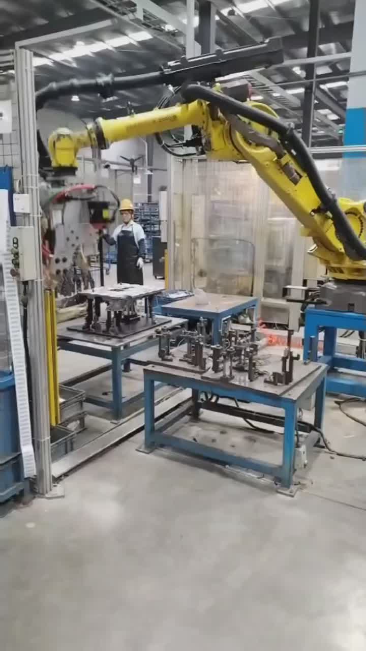
Gun motion around a clamped assembly
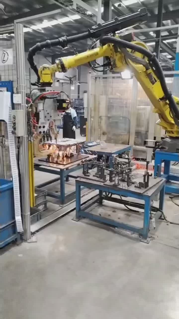
The footage shows a yellow industrial robot carrying a large spot-welding gun over a clamped metal assembly. The robot changes pose between fixture locations. Visible spark bursts occur at several tool-to-work areas, supporting an active resistance spot-welding operation rather than an empty motion demonstration.
How will electrode condition be managed after production starts?
Electrodes are part of the process, not permanent geometry. Their condition is affected by cooling, tip shape and material, alignment, impact, weld settings and the maintenance strategy. As the contact face changes, simply repeating the same robot position does not guarantee the same current density or joint result.
The quotation should identify how the cell will deal with this change. Questions that materially affect scope include:
- Is tip dressing performed in the cell, and can the gun reach the dresser without unsafe or awkward motion?
- How is electrode alignment checked after dressing or replacement?
- What triggers maintenance: a production count, a monitored condition, an inspection result or an agreed combination?
- If the control strategy changes current as electrodes wear, who defines and validates that schedule for the actual material stack?
- What records will connect electrode service and welding conditions with inspection results?
There is no useful universal dressing interval to copy into every project. Coatings, sheet materials, joint design, settings and production conditions alter electrode life. The procurement requirement should therefore ask for a validation method and maintainable access, not an unsupported number of welds per tip.
What test will prove the joint, and when will it be repeated?
Visual appearance and sparks cannot carry the acceptance decision. Resistance spot-welding quality control normally combines controlled production inputs with periodic joint confirmation. Destructive peel or chisel-type tests are established confirmation methods for suitable sheet assemblies. Ultrasonic examination can be useful in some applications, but its interpretation depends on factors including indentation, material and thickness and requires suitable equipment and trained interpretation.
That means “non-destructive inspection available” is not a complete acceptance plan. The buyer and supplier should agree which test applies to the component, what constitutes acceptance, how samples represent production, and what event requires a repeat test. Sampling frequency follows the part requirements, production volume and control plan.
A sensible commissioning sequence begins with the actual material stack and surface condition. Establish welding conditions on representative coupons or parts, then confirm them using the agreed joint test. Run the complete robot and fixture sequence on representative assemblies. After the maintenance action expected in production—such as dressing or electrode replacement—repeat the relevant alignment and joint confirmation. This tests recovery, not merely the best initial setup.
Which records make troubleshooting possible?
Consistency depends on more than the gun. Material and fit-up, tooling and electrodes, welding conditions, machine checks and periodic destructive-test records all contribute. A procurement specification should say which of these data need to be retained and how they identify the part, weld schedule and electrode state.
When a later test fails, those records help separate several possibilities. The part stack may have changed; the fixture may no longer present the sheets correctly; electrode faces may be worn or misaligned; cooling may be impaired; or welding conditions may have changed. Without traceable records, teams often respond by increasing current or touching up positions without showing that they addressed the cause.
Keep the record set proportional to the risk and production system. The objective is not paperwork for its own sake. It is the ability to connect an unacceptable joint with the material, tooling, settings, maintenance state and test evidence needed to correct it.
Put the difficult spots and the maintenance event into acceptance
Do not let acceptance consist only of repeated cycles on the easiest weld. Select the joints with the tightest gun access, the most demanding sheet stack or the greatest fixture interaction. Then include the maintenance action that production will actually require. A cell that passes before electrode service but cannot restore alignment or quality afterward is not yet demonstrating maintainable production.
For an EVST spot-welding discussion, send the weld-point layout, sheet materials and thicknesses, surface condition, fixture photographs and current joint acceptance requirement. EVST can use them to structure a discussion around gun access, maintenance provisions and a representative sample-validation scope. Discuss a robotic spot-welding cell with EVST.
Method: application-footage review and independent welding-technology guidance on electrode care, process consistency and joint testing. Editorial policy · Corrections policy · Terms of use