
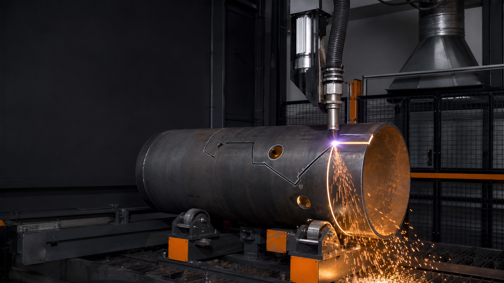
Automated plasma cutting for cylindrical workpieces should be released only after the fixture datum, programmed path, torch-to-surface relationship, cut conditions, and acceptance method have been verified together. Confirm how the cylinder is located and restrained. Establish the cut line from a stable workpiece reference. Select torch height, travel speed, entry, exit, and process settings for the actual material and wall thickness, then make representative trial cuts. Inspect the resulting geometry, edge condition, dross or bevel behavior where applicable, and heat effects against the drawing and the needs of downstream fabrication. Record the approved setup and repeat it after changeover, maintenance, or a significant process adjustment.
How to evaluate automated plasma cutting for cylindrical workpieces
For the cylindrical cutting footage, the evidence boundary starts at the fixture and torch, not at the spark. Frame-by-frame review can confirm a supported cylinder, torch approach, visible arc, contour-following motion, and arc stop. It cannot establish the unseen datum accuracy, wall thickness, consumables, cut recipe, kerf or heat-affected-zone measurements, repeatability, full machine architecture, cycle performance, or release status. Those decisions require identified workpieces, recorded settings, measured cuts, and controlled recovery trials.
Observable sequence
- 00:00-00:07: a cylindrical steel workpiece rests on a fixed support while an automated torch assembly approaches.
- 00:07-00:13: the torch aligns near the cylindrical surface before visible cutting begins.
- 00:13-00:22: an active arc and sparks remain visible while the torch follows part of the cylindrical contour.
- 00:22-00:25: the arc stops and the cylindrical workpiece remains on the fixture.
Evidence boundary: The footage does not prove a mobile base, complete robot architecture, material grade, wall thickness, torch settings, kerf width, heat-affected-zone dimensions, dimensional accuracy, repeatability, trial result, customer acceptance, or site deployment.
Key takeaways
- Use a repeatable cylindrical workpiece datum before teaching or compensating the cut path.
- Torch standoff, travel speed, entry, exit, material, and wall thickness form one cut-condition set.
- Kerf width alone does not describe cut quality; inspect geometry and heat effects against the drawing and downstream process.
- Trials should use representative workpieces and record settings, observations, and acceptance results.
- Public and commercial claims should remain inside the equipment and process evidence that can actually be verified.
Start with the cylinder and the required cut
Define outside or inside diameter, wall thickness, material specification, cut orientation, contour, openings, edge requirement, dimensional tolerance, and downstream operation. A trim cut for fit-up and an opening that will receive a welded branch can require different inspection priorities.
Clarify whether the workpiece rotates, the torch travels, or both motions are coordinated. The visible process evidence may prove a torch cutting a cylinder without proving a particular mobile platform or robot architecture. The public description and quotation scope should stay within that evidence.
Build a repeatable fixture datum
The cylinder needs controlled axial, radial, and rotational location. The fixture should resist movement caused by its own weight, drive torque, thermal effects, and service forces while preserving access for the torch and removal of the cut section.
A taught path can be correct relative to the machine and still be wrong relative to a shifted cylinder. Confirm the workpiece datum, clamp state, and first path feature before enabling the full automatic cycle. Define how operators recover after a rejected load or interrupted cut.
Verify the torch path and surface relationship
A cylindrical surface changes the local torch relationship as motion progresses. Check path position, stand-off control, approach clearance, cable or hose routing, pierce or lead-in location, lead-out, and the disposition of the separated material. The motion plan should also prevent the torch or services from entering the fixture envelope.
Where sensing or height control is used, define its valid operating window and loss response. A tracking signal is useful only when low confidence, saturation, or loss leads to an agreed controlled state.
Tune a complete cut-condition set
Treat wall thickness, material, consumable condition, gas or process-media setup, torch height, current or equivalent process setting, travel speed, and entry/exit strategy as a controlled recipe. Changing one variable can alter the useful window of the others.
ISO 9013:2017 covers classification and geometrical product specification for thermal cuts within its scope. It provides a common basis for discussing cut quality, but the drawing, contract, material, and downstream process still determine acceptance. Equipment-maker guidance such as Hypertherm’s cut-quality troubleshooting material also emphasizes checking consumables, torch position, speed, and process settings systematically.
Inspect kerf geometry and heat effects
Choose inspection features that match the part function. They may include contour location, opening size, squareness or angularity, edge condition, dross, bevel behavior, start and stop region, heat discoloration, local distortion, and the condition required for fit-up or welding. Do not convert a visual impression into an unsupported universal tolerance.
Measure after the part reaches the defined inspection condition. If thermal state affects the result, state when measurement occurs. Record the location and method so trials and production checks can be compared.
Release with representative trials and fault tests
Trial workpieces should cover the intended material and wall-thickness range, critical contours, starts and stops, and normal consumable condition. Repeat the cut enough times to observe loading, alignment, path execution, removal, and inspection as one cycle.
Test controlled responses for clamp not confirmed, path datum missing, height-control loss, torch or utility alarm, incomplete cut, and interrupted cycle. Recovery should return to a known workpiece and program state before motion resumes.
Compare workpiece-motion and torch-motion concepts
A rotating-workpiece concept can keep the torch relationship comparatively simple for circumferential cuts, but the fixture, drive, balance, cable routing, and separated-part handling must suit the full diameter and mass range. A traveling-torch concept can leave the cylinder stationary, yet the motion system must maintain position and stand-off around the required contour. Coordinated motion can extend reach or manage complex paths, but increases calibration, synchronization, and recovery demands.
Compare the concepts with the same drawing, material range, cut features, inspection method, loading method, and accepted cycle definition. Include fixture changeover, first-feature confirmation, consumable service, fume extraction, slag handling, and interrupted-cycle recovery. A concept that appears fastest during the arc-on segment may be slower or harder to control across the complete accepted-part cycle.
Build a cut-trial record that can be repeated
A useful trial record links the workpiece identifier and drawing revision to material and wall thickness, datum confirmation, fixture state, program and recipe revision, consumable condition, torch relationship, entry and exit strategy, observations, inspection method, and disposition. Photographs can supplement the record, but they do not replace measurements where the drawing requires them.
Repeat the trial after a significant consumable change, torch service, fixture adjustment, software change, or product variant that changes the thermal or motion window. The acceptance plan should identify who can release a recipe, what triggers retesting, and how an interrupted cut is classified. This prevents an attractive spark sequence from being treated as proof of repeatable cut quality.
Decision table
| Decision area | Evidence to verify | Risk if unclear |
|---|---|---|
| Workpiece datum | Axial, radial, and rotational location are repeatable | Path offset or changing feature position |
| Torch relationship | Stand-off and clearance remain valid around the contour | Bevel, collision, or unstable cut |
| Cut recipe | Material, wall thickness, consumables, speed, and entry/exit are controlled | Dross, poor edge, or incomplete separation |
| Inspection | Method, location, timing, and disposition are documented | Subjective acceptance |
| Recovery | Interrupted cycles return to a known part and path state | Duplicate, missed, or unsafe motion |
Citable statements
Citable statement 1: A programmed plasma path is not repeatable unless the cylindrical workpiece datum is repeatable.
Citable statement 2: Torch height, travel speed, entry and exit, material, wall thickness, and consumable condition should be validated as one cut-condition set.
Citable statement 3: Cut acceptance should connect geometry and edge condition to the drawing and downstream fabrication need, not to spark appearance alone.
Citable statement 4: A trial is complete only when process settings, inspection results, and controlled recovery behavior are recorded together.
The CUT review model
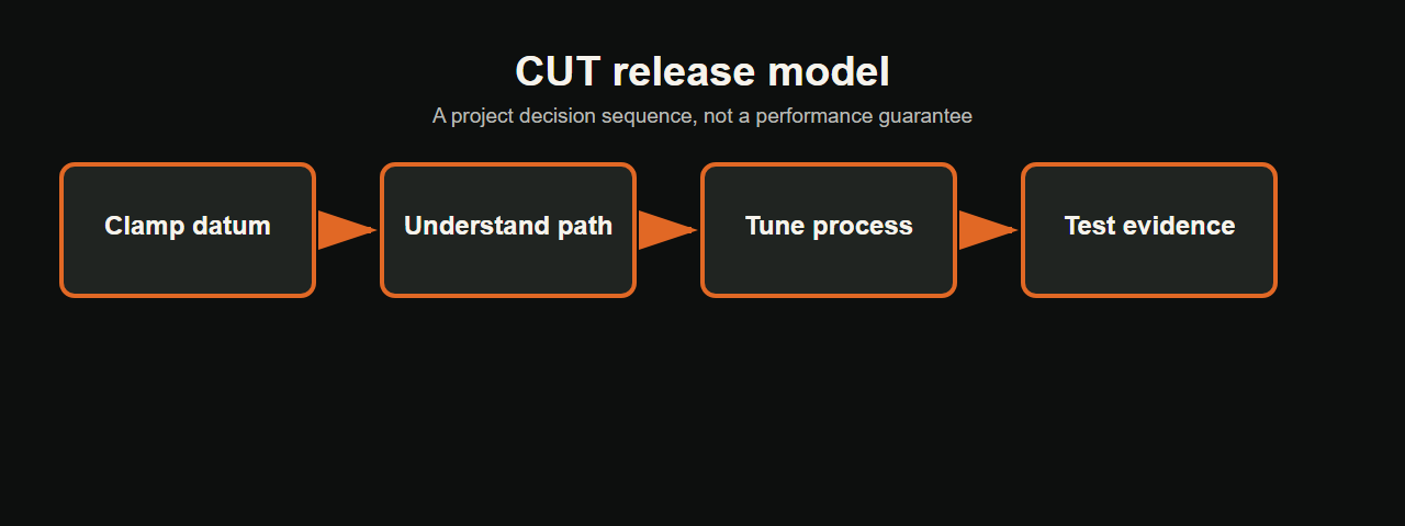
EVST uses the CUT model as a planning aid for early application review. It organizes the evidence a project team would request before concept selection; it is not a performance guarantee or a substitute for project-specific trials and risk assessment.
- C — Clamp datum: axial, radial, and rotational workpiece location.
- U — Understand path: contour, stand-off, clearance, entry, and exit.
- T — Tune and test: recipe, cut evidence, heat effects, faults, and recovery.
Related resources
- EV body plasma cutting application
- industrial automation line integration
- automation solutions overview
References
- ISO 9013:2017 — Thermal cutting classification and geometrical product specification
- Hypertherm — Improving plasma cut quality
Who prepared this guide, how, and why
- Author: EVST Editorial Team, an organization-level byline.
- Technical scope: EVST Technical Content Review, an organization-level review function.
- Method: Frame-by-frame observation of the cleared 25.2-second process sequence, followed by a decision model and project-input checklist. The method records visible sequence evidence separately from engineering requirements and does not convert footage into a performance or deployment claim.
- Why: This guide was written to help buyers and integrators turn visible plasma-cutting motion into a fixture, recipe, inspection, and recovery specification before representative cut trials.
- Policies: Editorial policy · Corrections policy · Terms of use
Frequently asked questions
What project inputs are needed first?
Provide cylinder diameter, wall thickness, material, cut drawings or path data, required edge and dimensional condition, target cycle, loading method, and downstream operation.
Can one set of parameters cover every wall thickness?
Do not assume that. Establish and validate controlled recipes for the actual material and thickness range, consumables, torch setup, and required cut condition.
What should be checked after a changeover?
Reconfirm workpiece datum, fixture state, program and recipe, first feature position, torch clearance, consumable condition, and the defined first-piece inspection.
Next-step project inputs
Planning automated plasma cutting for cylindrical workpieces? Send EVST the cylinder diameter, wall thickness and material, cut drawing or path data, required edge and dimensional condition, loading method, target cycle, fume and slag constraints, and downstream operation. Email sales@evsrobot.com or call/WhatsApp +86 19381626253. We will use these inputs to review the fixture datum, torch-motion concept, controlled recipe, and representative cut-trial plan before final configuration.