
A useful robotic coating brief identifies the required finish on each surface, including corners, recesses and hanging contacts. A single finish description for the whole part can leave those regions ambiguous. Mark their requirements before comparing spray paths, so the process team can distinguish a difficult surface from a surface that was never specified.
Turn the part drawing into a surface map
In the video at 00:05, a green robot approaches a hanging workpiece from the side. The lower view at 00:18 brings another portion of the part and its support into the discussion. These observations establish a useful starting question: which surfaces must the coating reach in this hanging arrangement? They do not establish coating thickness or the condition of concealed faces.
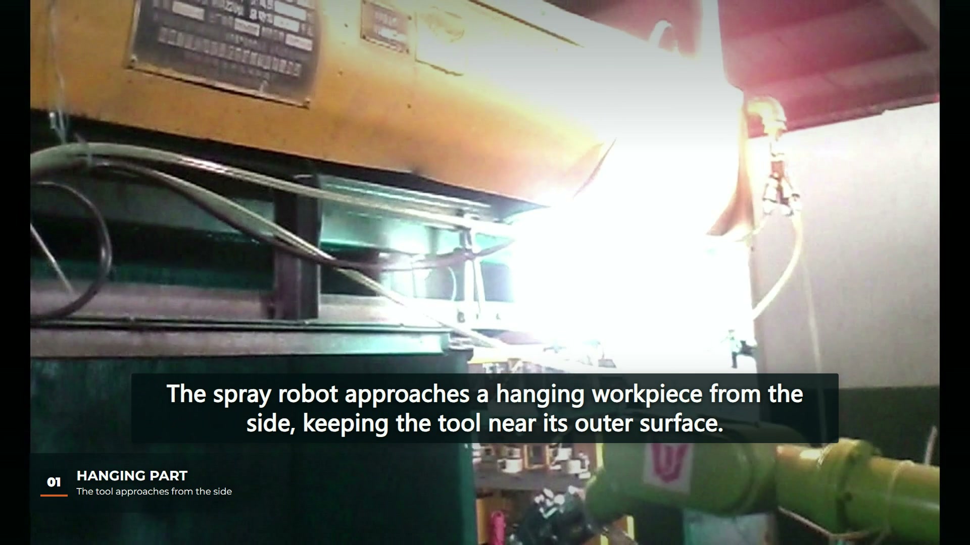
Use the drawing’s existing feature references to separate broad faces, protruding edges, recessed regions and suspension contacts. Give each region a requirement owner and a way to resolve uncertainty. A contact patch may be permitted to remain uncoated in one application and unacceptable in another; that is a product requirement, not a decision to leave to the robot programmer.
| Region in the proposed part | Clarification to record | What remains to be checked |
|---|---|---|
| Broad exposed face | Required finish and inspection location | Whether the chosen process meets that requirement |
| Corner or protrusion | Which adjacent faces require coverage | Local coverage under the proposed hanging orientation |
| Recess or rear face | Whether it is included in the coating scope | Access and the appropriate inspection view |
| Hanging contact | Permitted contact area and any finish exception | Agreement on handling or later treatment of that area |
These are suggested brief fields, not observations of completed checks in the filmed installation.
Keep geometry guidance within its scope
Graco’s spray-technique guidance explains how changing gun angle and distance can affect coverage. Its homeowner airless-spraying distances and overlap figures should not become settings for this robot. The relevant planning principle is narrower: a corner changes the relationship between the tool and the local surface, so its requirement deserves explicit attention.
A published Sames robotic painting solution describes shaping-air adjustment to adapt the spray pattern to a part. That is one equipment example. It shows why a coating discussion may involve applicator configuration as well as robot motion; it does not identify the applicator or available functions in this video.
Choose samples by the unanswered requirement
For a proposed application, a sample plan can follow the surface map. If the uncertainty concerns a recess, a result on the broad front face does not answer it. If suspension contacts are the issue, record the tested hanging arrangement alongside the inspection result. Avoid declaring the entire part acceptable when only an easily observed region has been examined.
This requirement map precedes the motion checks discussed in our robotic spray-path dry-run guide. The map defines what the coating must achieve; the dry-run review addresses how the equipment approaches the part. Neither substitutes for the subsequent coating assessment.
EVST’s editorial view is that an unresolved finish requirement should stay visible in the brief. A marked part drawing, actual hanging arrangement and region-specific inspection expectations make that uncertainty easier to resolve without turning a smooth spray motion into a claim about coating quality.