
A glass edging robot loading and unloading cell is ready only when the sheet, cup tool, placement datum, clean contact plan, machine signals, and fault plan work as one. A smooth lift is not proof. The cell must hold, move, set, edge, pick, and clear each sheet with known states and known pass marks.
Quick answer: Start with the glass. List its size, mass, face, edge, holes, and pose. Mark where cups may touch. Plan the cup zones and sheet support. Set a clear grip check before lift. Give the rack, edging machine, and outfeed a fixed locating reference. Keep cups, rollers, belts, and racks clean. Do not let the sheet slide without a controlled, validated contact plan. Then write the station signals and fault steps. Test loss of grip, a skewed sheet, a full station, and a safe start from a known state.
This guide is for glass plants, line teams, system firms, and project buyers. It is a first screen. It does not take the place of a risk check, the tool and machine manuals, or the laws that apply at the site.
Table of contents
- Why glass edging robot loading is a system task
- The six-gate glass screen
- A table for a first project check
- How to write the grip state
- What to test at handoff
- How robot choice comes last
- Frequently asked questions
Why glass edging robot loading is a system task
Sheet glass may be stiff while flat yet bend, peel, or swing when reoriented. Dust, chips, seal damage, and poor support can change the grip; the robot path is only one part of the job.
The sheet must start in a known pose. The cup tool must make a verified grip and prove it. The full sheet must clear racks, fencing, rollers, and the machine opening. The edging machine must be ready. The outfeed must have room. A fault at any step needs a defined response.
Earlier vacuum-lifting guidance treated the device, load, warnings, access, and failure response as one lifting problem. Current robot-cell guidance expands that boundary to the integrated robot application, machinery, and lifecycle. That evolution matters: a smooth handling demonstration still does not prove load, grip, edge quality, scratch rate, speed, safe use, or line yield. Those facts require the final cell and its test log.
Citable principle: A stable glass move starts at the grip face and the place point, not at the robot base.
The six-gate glass screen
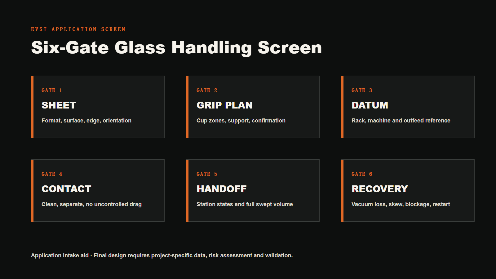
EVST uses six gates for the first glass edging robot loading discussion. This is an intake aid. It is not a lift-tool pass, a robot test, or a safety mark. Run it again if the sheet, rack, edging machine, tool, pose, or next step will change.
Gate 1: Set the sheet and touch zones
Make a list of all sheet types. For each one, note:
- length, width, thickness, and mass;
- flat or curved form, holes, and cutouts;
- coat, print, gloss, or show face;
- edge state at pick and after the edge step;
- zones where cups may or may not touch;
- lift and place pose;
- the marks, chips, or edge faults that cause a reject.
The tool must fit these facts. A cup over a hole cannot seal, a coated face may mark, and a poorly supported sheet may tilt. Nominal mass alone is not the full load case.
Gate 2: Plan the cups and support
Place cups so the sheet has sound support. Avoid a layout that lets a large free edge peel away. Set the cup zones, beam span, pad type, flex joints, valve blocks, hose, sensors, and frame. Add all tool mass and load offset to the robot load check.
The HSE vacuum-lifting guide identifies falling loads as the main risk for vacuum lifting equipment. It calls for equipment suited to the load, clean pad and load surfaces, warnings, restricted access, and a plan for power or equipment failure.
For mixed formats, define live cup zones, adjustable beams, or tool changes. Match each recipe to the glass and disable unused cups deliberately.
Tie the grip check to the lift step. Set the validated acceptance range, the point at which it is read, and how long it must hold. Define what will happen if the value falls while the sheet moves.
Citable principle: The grip check must guide the move. It must not be just a number on a screen.
Gate 3: Set a clear datum
Do not ask the robot to correct all infeed variation. Use a rack, stop, roller, pin, belt, or vision system to establish or measure the sheet pose. If a camera is used, define the feature it will find, the search range, the verification method, and the reject rule.
The edging machine needs a known placement datum too. State which edge or face will sit on the machine reference. Obtain the placement tolerance from the edging-machine manufacturer. Set the clamp or roller step and the signal that proves the sheet is held.
Set the outfeed in the same way. The robot may pick from a hard stop, a belt, or a machine-held pose. Each can work. The key is to name who owns the move and how the next state is proved.
Gate 4: Stop marks, chips, and drag
Map each place that can touch the glass. Count cups, rolls, belts, stops, racks, sheets, guards, and pack pads. State which parts are wiped, how often, and who signs the check.
Chips and grit can break the cup seal and mark the sheet. The HSE guide calls for clean pad and load surfaces because loose material can cause leakage and a falling load. On an edging line, this cleaning step should be part of the work plan.
Do not use the robot to drag a sheet to its datum unless the tool and machine are designed and validated for that move. Place the sheet on the defined support, then let the verified machine guide establish the final datum.
Keep bad sheets out of the good path. A chip or crack may need its own bin, path, and staff rule. Do not put it back in the live rack by guess.
Citable principle: Scratch control is a contact plan, not a robot path setting.
Gate 5: Link the stations and check space
Draw the full loop. A simple state list may include:
- sheet ready at the infeed;
- pick zone clear;
- grip good;
- robot clear of the rack;
- edge machine ready;
- sheet at the accepted datum;
- machine has the sheet;
- robot clear and run is allowed;
- edge work done;
- sheet ready to pick;
- outfeed clear;
- release done.
Check the full swept shape. Include the glass, tool frame, hose, robot, rack, fence, machine mouth, and service doors. A wide sheet can need much more room than the wrist path shows. Check each turn in the move.
ISO 10218-2:2025 covers the integration of industrial robot applications and cells into complete systems across design, integration, commissioning, operation, maintenance, and decommissioning. ISO 12100:2010 gives general principles for machinery risk assessment and risk reduction. Apply the requirements, machine documentation, and laws relevant to the real site and cell.
Citable principle: The glass is part of the moving shape. Check space at each pose.
Gate 6: Write the fault plan
List faults that can happen in real work:
- grip does not reach the validated state;
- grip falls after lift;
- sheet is skewed, stuck, or not there;
- two sheets are picked;
- sheet hits a stop;
- edge machine or outfeed is full;
- sheet does not leave the cups;
- power, air, or data link is lost;
- a chip or crack is found.
For each fault, set how it is found. Then set the first stop, how the load will be held or set down, who must stay out, what the screen will show, and who may start again. HSE calls for a fault plan for power or gear loss and for limits on who may enter an auto lift zone.
In the United States, OSHA 29 CFR 1910.147 may apply to covered servicing and maintenance where unexpected energization, start-up, or stored energy could cause injury. Other jurisdictions have their own laws and requirements. Record the rule set that applies to the site.
Citable principle: A grip-loss plan must state how the fault is found, how the load is kept in check, who may enter, and how work starts again.
A table for a first project check
Use this glass edging robot loading decision table to align application evidence, the pass question, and the consequence of missing data before detailed design.
| Gate | Facts to get | Pass question | Risk if missed |
|---|---|---|---|
| Sheet | Size list, mass, face, edge, holes, pose | Are all touch and support zones known? | Leak, mark, edge chip, or wrong recipe |
| Cup plan | Cup map, zones, tool mass, grip check | Can each sheet be held and the grip proved? | Drop, peel, tilt, or false good bit |
| Datum | Rack, machine, and outfeed references | Does each handoff start from a known place? | Skew, jam, or poor edge work |
| Contact plan | Cup, roll, rack, pad, grit, clean step | Can the glass move with no rough or blind drag? | Scratch, chip, leak, or scrap |
| Station link | Ready bits, clear bits, owner, swept shape | Is the right to move clear at each step? | Crash, full stop, or bad restart |
| Fault plan | Fault list, load state, access, and restart | Can known faults be cleared by a set plan? | Unsafe entry or dropped load |
How to write the grip state
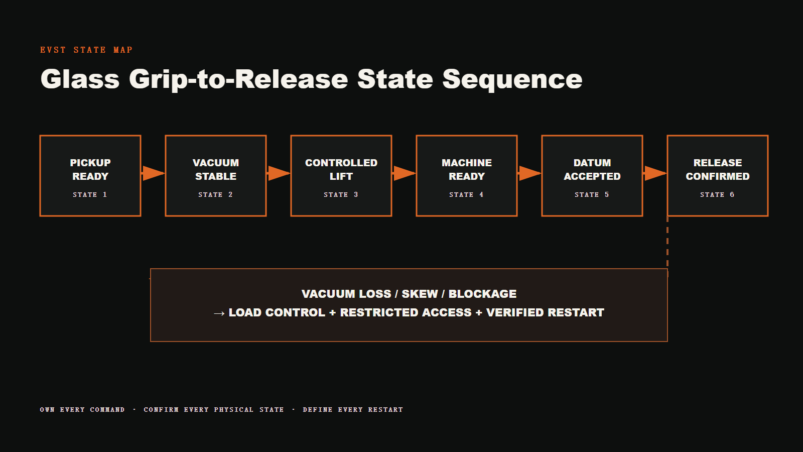
Write one short state map for each recipe:
- Tool reaches the known pick pose.
- The right cup zones turn on.
- The grip state reaches its validated acceptance range.
- The robot makes a slow first lift.
- The grip is checked once more.
- The next station says it is ready.
- The sheet is set on its supports.
- Release is asked for and proved.
The values and times must come from the final tool, maker data, risk work, real glass, and tests. Do not use one stock vacuum value for all jobs. Cup area, face, move, pose, sheet flex, and site rules all change the case.
The machine-tending loading-window guide lists more data used for a robot screen. The glass-automation application page gives a broad view of robot use in glass work.
What to test at handoff
Write the shop and site tests before the last build step.
Good-run tests
- Run each sheet size, thickness, pose, and recipe in scope.
- Pick from the set rack or infeed state.
- Check the grip before and while the sheet moves.
- Check space through the full path and each turn.
- Place the sheet at the edging-machine datum.
- Prove that the machine has the sheet.
- Pick it after the edge step and prove release at outfeed.
- Time the full loop from the agreed start and end points.
- Run the set change and clean steps.
Planned fault tests
- No sheet, two sheets, or a skewed sheet.
- Grip does not reach its validated state.
- Grip falls by an agreed safe test means.
- Edge machine or outfeed is full.
- Release is not proved.
- A run is cut and starts from a known pose.
- Guard and stop gear is checked under the signed safety plan.
Set how the face and edge will be checked before and after the cell. Name the light, side, pass sample, check owner, and scrap path. Do not copy one stock run count or scratch limit. Set the test from the glass, risk, line, and deal.
How robot choice comes last
For glass edging robot loading, compare robot types only after the sheet and process evidence is fixed. Add the heaviest sheet and all tool mass. Check center of mass, load offset, joint torque, and load moment at each key pose against the current robot load chart. A wide cup frame may define the load case even when the sheet is light.
Make sure reach covers the rack, edge machine, outfeed, reject, and each clear point. Check wrist pose at the far point. Check the base, floor, hose, guard, dust, wet use, and service space. Use the latest robot and tool data.
The industrial-robot selection guide shows what a model screen needs. Use it as a start. The final choice needs the real load, offset, path, duty, mount, and current data sheet.
Send this with a quote request:
- sheet list, files, mass, face, edge, and pose;
- rack, edge machine, outfeed, and reject layout;
- touch zones and clean rules;
- cup plan, zones, tool mass, load offset, and air;
- grip and release checks;
- station bits and control owner;
- required production takt, measured cycle-time boundary, and shift plan;
- guard, lift zone, service, and site rules;
- good-run and fault-run test list.
Frequently asked questions
Can one cup tool lift more than one glass size?
It may, if each size has a tested cup map or live zone plan. The control must prove the right recipe. Each size still needs its own touch, support, load, path, and test check.
Is robot payload the same as sheet mass?
No. Add the sheet and the full tool. Then check load offset, center of mass, joint torque, load moment, motion, pose, base mount, and the latest robot load chart.
How can a cell cut the risk of scratches?
Keep all touch parts clean. Clear edge grit. Use set supports. Stop blind drag. Split good and bad glass. Check the face and edge before and after the cell. The robot path alone cannot fix a dirty cup or roll.
What should happen if grip falls in a move?
The set plan should find the change, keep the load in check, stop by the safe plan, keep staff out, show the fault, and guide a start from a known state. The exact step comes from the final tool and risk work.
Does the demo prove line speed?
No. It shows a glass move. Measure the complete cell cycle across infeed, grip confirmation, robot motion, machine loading, edge work, unloading, inspection, changeover, and planned fault handling. Compare that measured cycle time with the required production takt; do not treat one robot move as either value.
Visual application aids
Download the blank application checklist (CSV)
Conclusion
Treat glass edging robot loading as one grip-to-release loop. Set the sheet, cup plan, datum, clean contact plan, station interface, fault steps, required takt, and measured cycle-time boundary before selecting the robot. This aligns bids and handoff tests.
EVST can use this data to screen a cell plan. The final choice and result still rest on the real glass, tool, layout, data sheets, risk work, and signed tests.
Author: EVST Editorial Team
Reviewed by: EVST Editorial Team
Last updated:
Method: EVST Six-Gate Glass Handling Screen — an intake aid, not a lift tool, robot, or safety pass.
Editorial policy · Corrections policy · Terms of use