
By EVST Editorial Team · Reviewed by EVST Editorial Team · Updated October 16, 2026
Method: case-video analysis and engineering references · Editorial Policy · Corrections Policy · Terms
A long rail-component fixture with many repeated clamp positions creates a different planning problem from a single large frame. Two robots may each reach several joints, but useful production depends on assigning stable work zones, presenting every joint consistently and defining what happens at the boundary between those zones.
Discuss your repeated-part welding application with the component drawing, joint map and fixture concept.
Read the fixture as a chain of stations
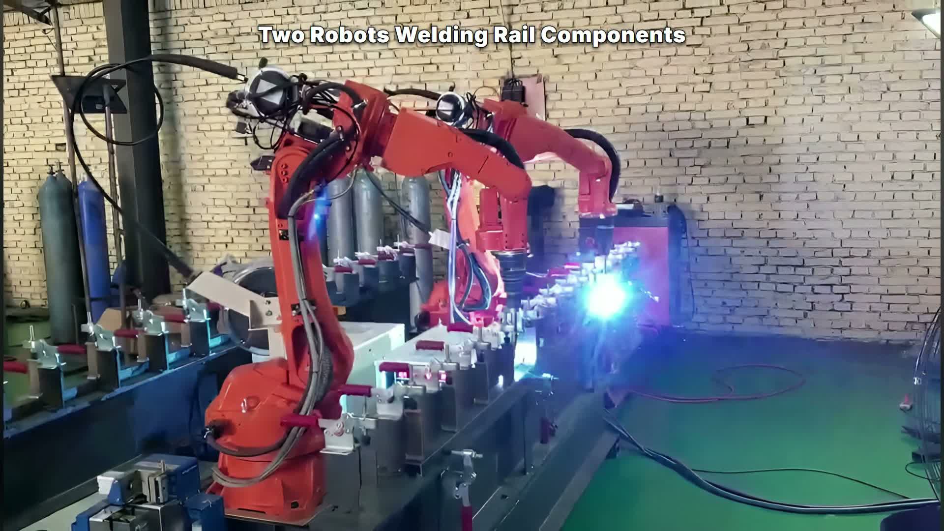
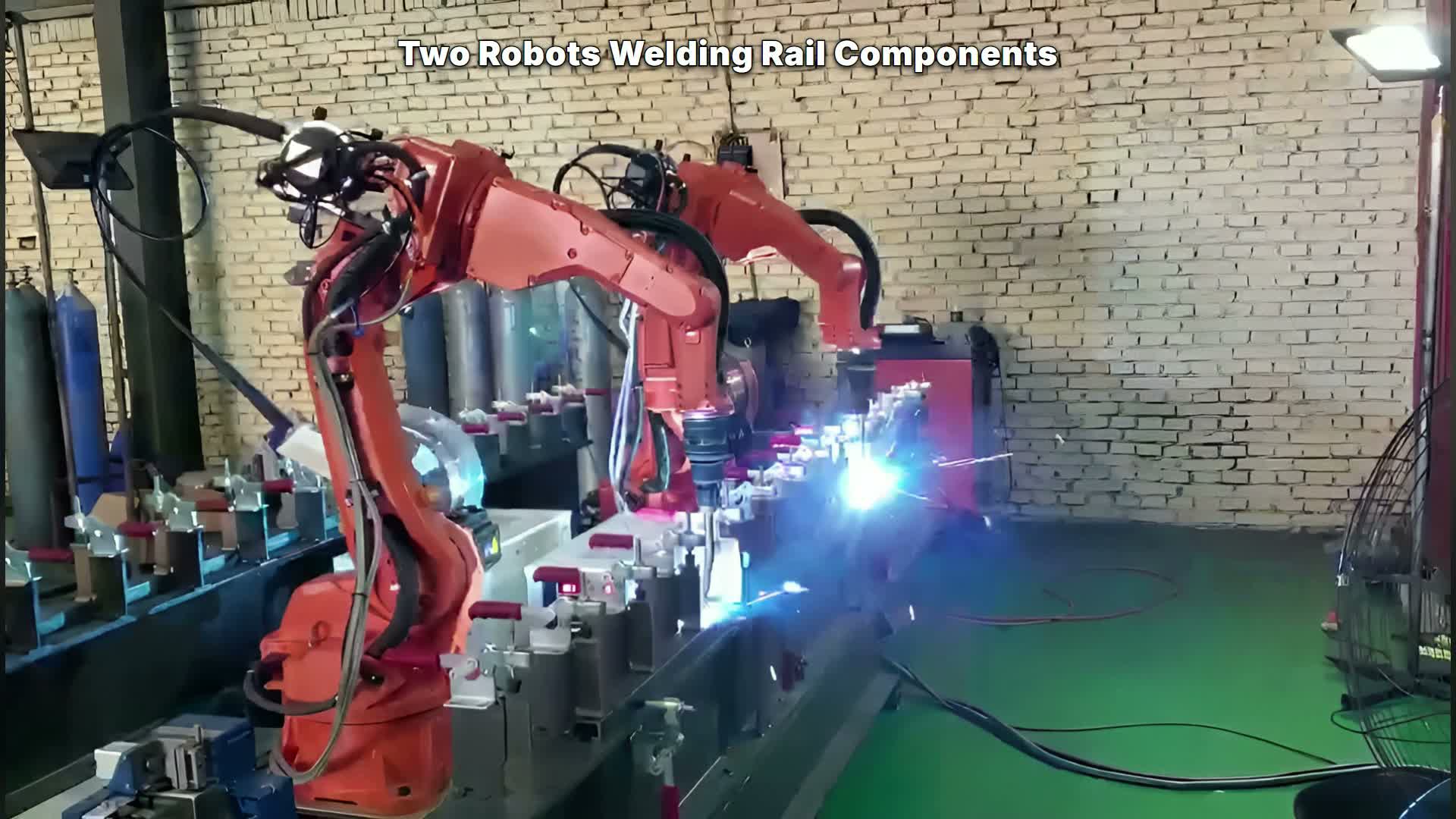
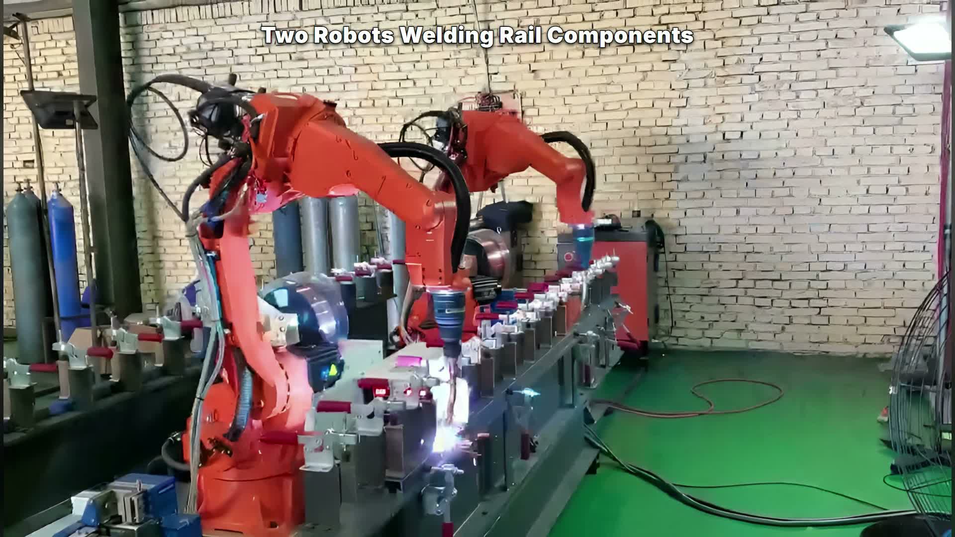
The case video keeps two orange robots, their tools and a long narrow fixture in view. EVST’s welding-workstation configuration guide provides related cell-level context for comparing robot count, fixture arrangement and safeguarding. The fixture contains many repeated clamp locations. Welding arcs appear at separated regions while the robots change position along the same line.
That visible arrangement suggests treating the fixture as a chain of stations rather than one continuous workpiece. Each station should have an identified joint set, clamp state, approach direction and exit direction. A station map gives programmers and reviewers a common reference when a joint is reassigned or a clamp position changes.
Divide work by stable joint families
An equal joint count is not automatically a balanced assignment. One joint family may require a longer approach, a larger wrist rotation or a retreat that crosses another station. Start by grouping repeated joints that share part orientation, torch direction and fixture access. Then assign complete groups to a robot where possible.
The aim is to reduce handoffs inside a repeated pattern. If both robots alternate at every clamp, the program gains more boundary states and recovery cases. A cleaner concept gives each robot a stable region or a stable joint family, then limits shared responsibility to a clearly defined boundary.
This division must be validated with the complete tool and cable envelope. The footage shows external dress packs, but it does not establish their allowable bend or routing limits.
Fixture consistency is a process input
Repeated clamp positions only help when they present the component consistently. A feasibility trial should check locating faces, clamp sequence, part seating and the accumulated variation from one station to the next. A reachable programmed point cannot correct an uncontrolled reference.
Review the fixture at the most constrained station, not only the easiest one. Include clamp handles, supports, cables and adjacent stations in the model. An ABB welding-cell layout provides a related example of reviewing robot, fixture, operator position and safeguarding together; the actual configuration still depends on the component and site.
Sequence boundaries need explicit states
The two robots work along one fixture, so the boundary between assigned zones deserves its own program logic. Define where each robot finishes its last joint, where it retreats, and what state permits the other robot to enter a neighboring station. Also define restart positions after a stop.
A useful sequence record names approach, process, retreat, wait and recovery states for each station family. This makes a boundary review concrete without claiming measured synchronization from the footage. A KUKA preconfigured-cell document likewise documents guarded access as part of the complete cell; site safeguarding must be engineered separately.
Validate the pattern, then the exceptions
Run a representative sequence across several adjacent stations. Record the fixture position, joint identifier, program revision and inspection result. Check the first station, middle stations, the zone boundary and the final station separately. These locations expose accumulated fixture variation and special transition moves.
Then test abnormal states: a missing component, an incomplete clamp, a stopped robot and a restart near the zone boundary. The response must be based on verified inputs and cell controls, not inferred from normal motion.
Inputs for a useful concept review
Provide the rail-component drawing, joint map, allowed welding directions, fixture and datum scheme, clamp sequence, tool and cable model, product variants, inspection method, volume target, available floor space and site safety requirements.
These inputs allow the team to compare joint-family assignments, check fixture consistency and build a sequence with reviewable boundary states. Contact EVST or email sales@evsrobot.com to review a two-robot welding concept.
Footage boundary: the video shows two robots welding along a long repeated-clamp fixture; it does not verify welding method, measured synchronization, joint geometry, weld quality, spatter level, cycle time, ownership or customer identity.