
A mobile cutting or welding unit does not arrive at a new workstation with a valid process coordinate merely because it reached the correct area. Docking error, floor condition, workpiece setup, tool state, and station geometry can all shift the relationship between the programmed path and the physical joint or cut.
Mobile robot coordinate re-registration is the controlled process of rebuilding that relationship before process execution. The objective is not to hide every physical error inside one correction value. It is to identify which frame moved, verify the new transformation, and prevent machining or welding until the required checks pass.
Key takeaways
- Arrival at a station does not create a valid process coordinate.
- Platform, station, workpiece, robot, and tool frames should be checked separately.
- The controller should store coordinate validity as a state.
- A move, collision, tool change, or uncertain reset can invalidate that state.
- Process energy stays disabled until representative points and boundaries pass review.
Direct answer: how should mobile robot coordinate re-registration work?
Mobile robot coordinate re-registration should rebuild the coordinate chain in a fixed order. First, identify the station and confirm the platform is docked. Next, measure the platform-to-station relationship. Then locate the real workpiece datum. Check the active robot base and tool-center calibration. Calculate only the correction that the project permits. Finally, test representative points, approach height, orientation, and path limits before process energy is enabled. The controller should mark the result as verified. It should also clear that state after movement, collision, fixture change, tool service, or any reset that makes the geometry uncertain. This approach keeps docking error separate from part and tool error. It makes faults easier to trace. It also stops an old transformation from being reused at a new station. Navigation can deliver the unit to the work area. Registration proves that the programmed path still matches the physical work.
Define the coordinate chain first
Most mobile process cells can be described with several linked frames:
- map or facility frame: the common plant-level reference;
- mobile-platform frame: the actual pose of the transported equipment;
- station frame: the repeatable reference for a work area or fixture;
- workpiece frame: the origin and orientation of the installed part;
- robot base frame: the manipulator’s reference relative to the platform;
- tool center point: the calibrated process point and orientation.
The commanded path is only meaningful when the relevant transformations between these frames are valid. If the platform moves, the workpiece is re-fixtured, or the torch is serviced, a different part of the chain may require re-registration.
ISO 9787:2013 defines robot coordinate systems and motion terms. It supports clear naming for alignment, testing, and programming. It does not set the accuracy limit for this application. The process and acceptance plan must set that limit.
Separate docking error from workpiece error
One common mistake is to touch a feature on the workpiece and apply the entire difference as a work-object correction. That can make one path appear correct while masking a platform pose error, a shifted fixture, or a tool-center change.
A better sequence is:
- locate or verify the mobile platform relative to the station;
- verify the station reference and fixture condition;
- locate the actual workpiece datum;
- confirm tool calibration status;
- calculate and apply only the permitted correction;
- validate representative points before enabling the process.
This layered approach also improves diagnosis. When a result drifts, the team can determine whether the change follows the platform, the station, the part, or the tool.
A practical re-registration workflow
1. Controlled arrival and docking
The platform enters the station and reaches its defined docking state. Record the station identity and confirm that the unit is in the expected zone. Mechanical locating features, localization sensors, or a combination may be used, but the final accuracy must be evaluated at the process point—not inferred from navigation accuracy alone.
2. Establish the station relationship
Measure known station features or fiducials. Use more than one feature when orientation must be resolved. The selected geometry should make it possible to detect an incorrect station, an implausible transform, or a reversed orientation.
3. Locate the workpiece datum
The fixture and the workpiece are not always identical references. If the manufacturing process permits part variation, locate features that represent the actual path. The sensing method must be suitable for the material, surface condition, joint geometry, and required process tolerance.
4. Check the tool state
Confirm that the active tool and calibration version match the program. After a torch collision, consumable replacement, mechanical service, or tool change, the previous tool-center calibration may no longer be valid.
5. Validate before process enable
Check representative points, safe approach height, path boundaries, and orientation. A dry run or reduced-risk verification method may be appropriate depending on the process and risk assessment. Process energy should remain disabled until the required validation states are complete.
Treat coordinates as state, not static configuration
The control architecture should know whether a coordinate is valid. A useful state model includes:
| State | Meaning | Permitted action |
|---|---|---|
| Unknown | no trusted relationship after arrival or reset | localization only |
| Located | station relationship measured | workpiece registration |
| Registered | workpiece and tool relationship calculated | validation move |
| Verified | checks pass within project limits | process may be enabled |
| Invalid | an event has broken confidence | stop process and re-register |
This prevents a restarted program from silently reusing a transformation that was calculated before the platform moved or before an abnormal event.
Citable statement 1: Mobile robot coordinate re-registration is complete only after the process frame has been measured and verified at representative points.
Citable statement 2: Navigation accuracy and process-path accuracy are different results because they use different coordinate chains.
Define invalidation events in advance
Coordinate validity should be cleared after events that can alter geometry or confidence. The exact list is application-specific, but typical triggers include:
- platform movement outside the verified docking state;
- collision or unexpected contact;
- emergency stop followed by uncertain physical movement;
- power loss where position retention cannot be demonstrated;
- fixture adjustment or workpiece re-clamping;
- tool replacement, repair, or recalibration;
- localization confidence below the project limit;
- manual jogging that changes the controlled setup.
Do not rely on an operator to remember every trigger. Where practical, the control system should invalidate the state automatically and require the defined verification sequence.
Acceptance criteria should cover more than point error
An acceptance plan may include:
- repeatability across multiple arrivals at the same station;
- performance across all intended stations;
- representative position and orientation checks;
- first-path and boundary verification;
- false-station and implausible-transform rejection;
- recovery after defined power, stop, and movement events;
- traceability of station, program, calibration, and correction versions;
- confirmation that process enable is blocked when coordinates are invalid.
The numerical tolerance must come from the process, joint geometry, cut quality, and risk assessment. There is no universal coordinate tolerance that fits every mobile cutting or welding application.
Citable statement 3: A coordinate tolerance is valid only when it is linked to the joint, cut, tool, and acceptance method of the real process.
The FRAME validity model
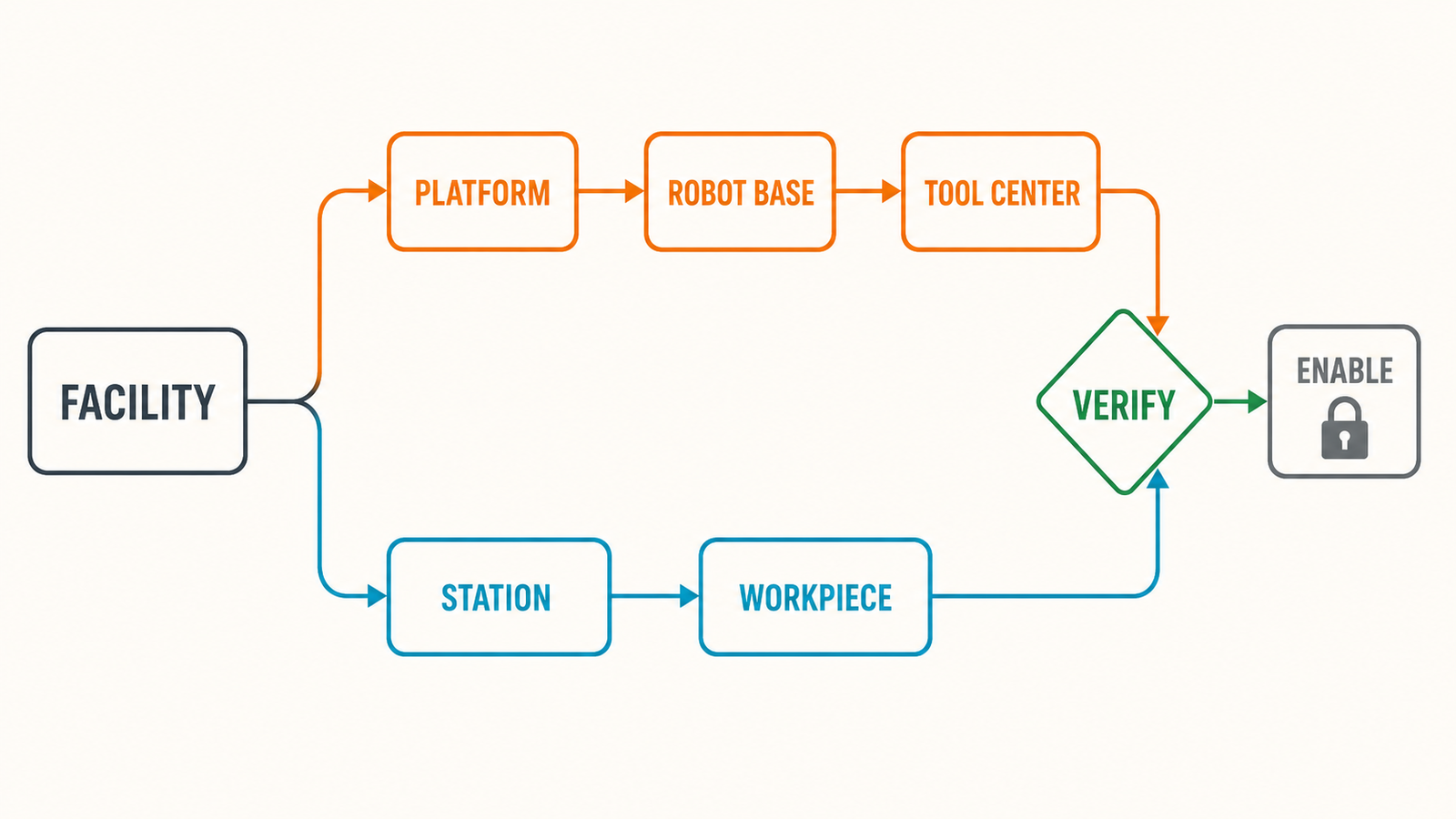
EVST uses a five-part discussion model for mobile robot coordinate re-registration. The name is FRAME: Facility, Robot platform, Actual workpiece, Measurement, and Enable.
- Facility: identify the station and its fixed reference features.
- Robot platform: measure the arrived platform pose and docking condition.
- Actual workpiece: locate the part that will be processed, not only the fixture.
- Measurement: check the robot base, tool center, and allowed correction.
- Enable: validate representative points before process energy is released.
Each part produces a record. A simple decision table keeps the control logic clear.
| FRAME stage | Pass evidence | If it fails |
|---|---|---|
| Facility | expected station ID and valid reference | reject the station state |
| Robot platform | docking and pose within project limits | re-dock or inspect localization |
| Actual workpiece | datum found and transform plausible | inspect part and fixture |
| Measurement | robot/tool calibration versions valid | recalibrate or select correct tool |
| Enable | test points and limits pass | keep process energy disabled |
EVST recommends storing the station ID, program version, calibration version, calculated transform, and result of the enable check. These fields support fault review. They also help prevent a program from using a valid transform for the wrong station.
The model does not set a universal accuracy number. EVST uses it to expose which decision needs a project limit. The customer and integrator can then tie that limit to cut or weld acceptance.
Citable statement 4: Coordinate validity should be a controlled machine state, not a number that remains trusted until someone remembers to clear it.
Safety and scope boundaries
Coordinate registration is not a substitute for risk reduction. The system still needs appropriate safeguarding, process-hazard controls, stop functions, and safe commissioning procedures.
ISO 10218-2:2025 addresses integration, commissioning, operation, maintenance, and decommissioning of industrial robot applications and cells. Its published scope states that it does not cover mobility-related hazards when robots or manipulators are integrated with mobile platforms. This is a narrow but important boundary. It does not mean that every other robot-cell integration requirement becomes irrelevant. It means the mobile architecture needs additional, application-specific safety analysis for the mobility hazards.
If the carrier is a driverless industrial truck, ISO 3691-4:2023 gives safety requirements and verification methods for that truck and its system. Its examples include automated guided vehicles and autonomous mobile robots. Its scope does not replace controls for the added cutting or welding hazards.
Data to request before integration
For a feasibility review, provide:
- station count and travel layout;
- floor, rail, or docking conditions;
- workpiece dimensions and allowable variation;
- fixture and datum strategy;
- required path position and orientation performance;
- proposed localization and sensing methods;
- tool type and calibration process;
- process hazards and safeguarding concept;
- required recovery scenarios and traceability fields.
This information makes it possible to design a coordinate chain and acceptance test before the software becomes tied to an oversimplified “one correction fixes all” approach.
Frequently asked questions
Is navigation accuracy enough for welding or cutting?
Not necessarily. Navigation brings the equipment to the station. Process accuracy depends on the entire relationship among the platform, station, workpiece, robot, and tool. That relationship should be verified at representative process points.
Can vision correct every docking error?
Vision can measure suitable features within its own field of view, resolution, calibration, and environmental limits. The project must still define what the correction represents and reject measurements that are incomplete or implausible.
Should the system re-register after every move?
If the move breaks the verified relationship, yes. The required depth of the routine may vary, but process execution should not rely on a coordinate state that is no longer trusted.
Build a verifiable coordinate architecture
EVST can help evaluate station geometry, localization, workpiece registration, robot/tool calibration, process enable logic, and acceptance testing for mobile cutting and welding applications. Share the station layout and process tolerance to begin a technical review.
Related resources
- Complete guide to robotic welding
- Robotic welding safety guide
- Offline programming, simulation, and digital twin guide