By the EVST Editorial Team · Last updated: June 9, 2026
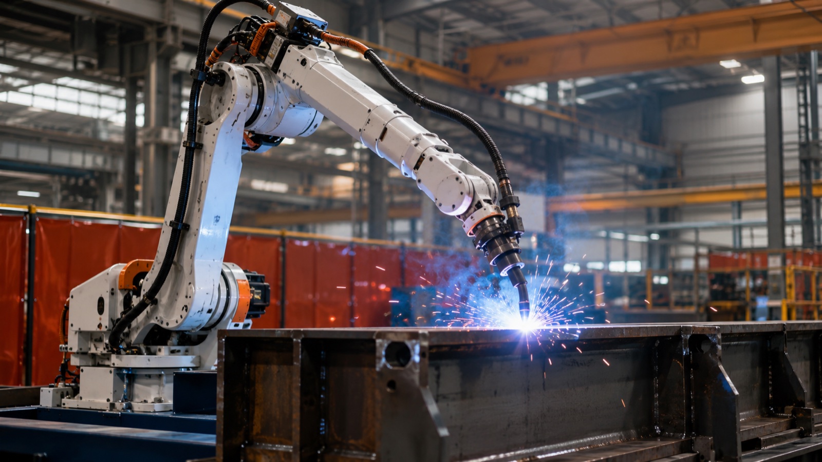
A welding robot is a 6-axis industrial arm fitted with a welding torch or gun. The three dominant processes in 2026 are MIG (GMAW) for high-deposition structural work, TIG (GTAW) for thin-gauge precision, and resistance spot welding for sheet metal. Payload ranges from 6 kg for a light MIG torch to 800 kg for automotive spot guns. Defect rates drop from 5 to 8 percent in manual welding to below 1 percent in well-calibrated robotic cells.
What a Welding Robot Is, and What It Is Not
A welding robot is the combination of three things that often get conflated: the robot arm itself (the manipulator), the welding power source and process equipment (torch, wire feeder, water cooler, or weld gun), and the cell-level integration (positioner, fixturing, safety enclosure, seam tracking, fume extraction). The arm without the process equipment is just an industrial robot; the process equipment without the arm is a manual welding station. The value of the system lives in the integration, not in any single component.
This guide covers 6-axis articulated welding robots used in heavy industry: automotive body-in-white, construction equipment, shipbuilding, pressure vessels, rail rolling stock, energy infrastructure, and large fabrication. It does not cover SCARA arms (insufficient reach for most weld envelopes), Cartesian gantries (used for very long seams in shipbuilding but a different design discipline), or hand-held cobot welders aimed at light-duty job shops. For a wider view that includes those formats, see our complete guide to robotic welding 2026.
According to the International Federation of Robotics 2025 World Robotics report, welding is the second-largest application segment for industrial robots after material handling, accounting for roughly a quarter of installations in heavy manufacturing economies. The mix has shifted: arc welding (MIG and TIG combined) has grown faster than spot welding over the past five years, because non-automotive heavy industry, where arc welding dominates, has industrialized faster than automotive body-in-white capacity has expanded.
The 6-Axis Architecture: Why Six Axes for Welding
A welding torch needs to reach an arbitrary point in space and present at an arbitrary orientation. Three axes give you the point. Three more give you the orientation. Six is the minimum for general 3D welding without compromise. Fewer axes force you to redesign fixtures or accept poor torch angles; more axes (7-axis arms with redundant elbow) help in cluttered environments but add cost and complexity.
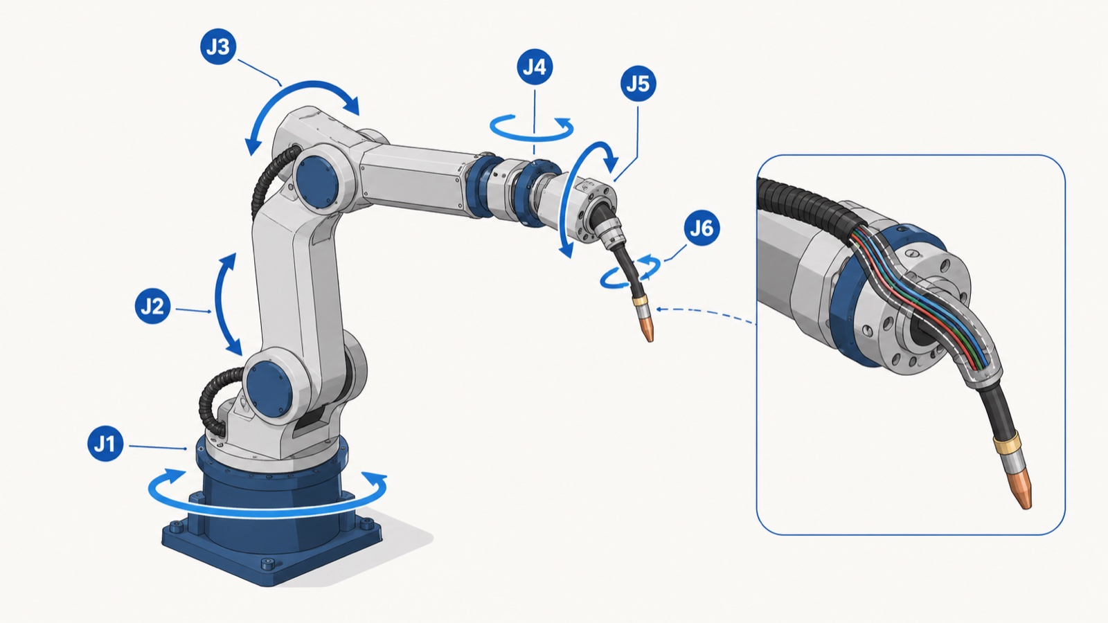
A typical 6-axis welding robot has:
- J1 — Base rotation: rotates the whole arm around a vertical axis. Determines lateral reach.
- J2 — Shoulder: lifts the lower arm. Bears the largest static torque.
- J3 — Elbow: extends the upper arm. With J1 and J2, sets the wrist position.
- J4 — Wrist roll: rotates the wrist around the upper-arm axis.
- J5 — Wrist pitch: tilts the torch up and down.
- J6 — Torch rotation: spins the torch around its own axis, used heavily for orienting the wire angle relative to the seam.
The wrist (J4-J5-J6) is what makes a welding robot different from a generic 6-axis arm. A “hollow wrist” design routes the welding cables, gas hose, and water lines through the inside of the arm, instead of slinging them externally. In practice, hollow-wrist arms last longer between cable replacements and reduce cable snags in tight workspaces. The trade-off is slightly lower wrist torque and slower wrist speed than an externally-cabled arm of the same nominal payload.
Payload classes in welding service in 2026 cluster around:
- 6 to 8 kg — light MIG torches with simple wire feed
- 12 to 20 kg — heavier MIG torches with synergic pulse, TIG with cold-wire feed, water-cooled torches
- 50 to 100 kg — heavy multi-process welding heads, narrow-gap welding
- 165 to 350 kg — spot welding guns in automotive body-in-white
- 500 to 800 kg — heaviest spot guns, multi-tool welding heads on heavy chassis
For broader context on China-based suppliers across these payload ranges, see our analysis of the top 10 industrial robot manufacturers in China for 2026.
MIG, TIG, and Spot: Process Comparison
The three dominant robotic welding processes each suit a different combination of material, thickness, joint type, and production volume. They are not interchangeable, and choosing the wrong process for the application is the most common reason robotic welding cells underperform.
| Attribute | MIG (GMAW) | TIG (GTAW) | Resistance Spot |
|---|---|---|---|
| Filler metal | Consumable wire (continuous) | Non-consumable tungsten electrode + separate filler rod | None (resistance fuses base metals) |
| Typical material thickness | 1 to 25 mm (multi-pass beyond) | 0.5 to 6 mm | 0.5 to 3 mm sheet pairs |
| Deposition rate | High (1 to 10 kg/hr) | Low (0.2 to 1 kg/hr) | N/A (point-by-point) |
| Heat input | Medium to high | Low to medium (controllable) | Very short pulse |
| Cycle time per joint | Seconds per linear cm | Slower, multi-pass for thick joints | 0.5 to 2 seconds per spot |
| Robot payload typical | 6 to 20 kg | 6 to 12 kg | 165 to 350 kg |
| Suited to | Structural steel, construction equipment, heavy fabrication | Stainless steel, aluminum, exotic alloys, pressure vessels, thin gauge | Automotive body-in-white, white-goods sheet assembly |
| Common defect mode | Spatter, porosity from gas coverage loss | Tungsten contamination, contour deviation | Cold spot, electrode wear, weld nugget undersize |
According to industry observations from heavy fabrication plants, MIG accounts for roughly 70 percent of arc welding robot installations because it covers the bulk of structural steel work where speed matters and joint geometry is relatively forgiving. TIG installations are smaller in count but disproportionately important in pressure vessels, aerospace, and stainless-steel food and pharma equipment, where weld quality has to clear non-destructive inspection.
Spot welding is concentrated in automotive: a single body-in-white line can have 200 to 400 spot welds, and a high-volume plant runs dozens of robots simultaneously. Outside automotive, spot welding shows up in white-goods (refrigerator and washing machine cabinets), electrical enclosures, and HVAC duct fabrication.
Heavy Industry Use Cases by Sector
Heavy industry deploys welding robots in patterns that differ by sector. The patterns are stable enough that buyers can use them as a starting reference when scoping a project.
Automotive body-in-white
Spot welding dominates body assembly. A modern line uses 150 to 300 KG spot guns on payload-matched 6-axis arms, often arranged in tandem on a single body-in-white frame to keep cycle times under 60 seconds per body. MIG and laser welding are growing for closures (doors, hoods) and roof joints. The defining constraints are throughput (cars per hour), positional accuracy (panel-to-panel fit), and traceability (every weld logged for warranty).
Construction and agricultural equipment
MIG is the dominant process for excavator booms, dump truck beds, tractor frames, and similar large weldments. Payloads are heavy plate (8 to 25 mm common), seam lengths are long, and joint preparation varies because parts are often cut and bent in-house with non-trivial tolerance. Seam tracking (laser or arc-sensing) is more important here than in automotive, because the part the robot is welding does not arrive in a precisely repeatable fixture.
Shipbuilding and offshore
Large-scale gantry-mounted MIG and submerged-arc welding handle the longest seams, but 6-axis arms on linear tracks handle complex assemblies, T-joints, and stiffener welds inside ship blocks. Heat input control matters because thick steel distorts under uneven heating. Multi-pass welding with seam tracking and adaptive parameter adjustment is standard.
Pressure vessels and energy infrastructure
TIG and narrow-gap MIG dominate here because every weld must clear radiographic or ultrasonic inspection. ASME Section IX and ISO 15614 qualified procedures govern parameter envelopes. Robotic cells often use orbital systems for circumferential welds on pipe, with 6-axis arms reserved for nozzle attachments, branch connections, and tube-sheet welds.
Rail rolling stock and heavy chassis
A mix of MIG (for bogie frames, body shells in aluminum or steel) and spot welding (for stainless-steel rail car bodies in some markets). High-strength low-alloy steels and aluminum extrusions are common; weld procedure qualification is rigorous. Linear tracks extending the robot’s reach across long carbody sections are common in this sector. For ground-rail integration patterns, see our overview of robot linear tracks for extended reach.
The Welding Cell: Components Beyond the Robot
The arm is roughly 30 to 40 percent of a complete welding cell budget. The other 60 to 70 percent is in the integration components that turn an arm into a productive welding system. Underspending on these components is the most common cause of disappointing returns.
- Power source and wire feeder. The synergy between the arm and the power source matters: digital communication (DeviceNet, EtherCAT, or proprietary protocols) lets the robot adjust current, voltage, and wire-feed speed on the fly. Modern pulsed MIG sources reduce spatter by 30 to 50 percent compared to constant-voltage systems on the same joint.
- Welding positioner. A 2-axis or 3-axis positioner rotates and tilts the workpiece so the robot always welds in the flat or horizontal position, where deposition rate and weld quality are highest. For weldments where the joint can be presented flat, a positioner roughly doubles the productive output of the same robot compared to fixed-fixture welding. See our welding positioner range overview for typical payload and tilt configurations.
- Linear track (7th axis). Extends robot reach for long weldments. Track lengths range from 2 to 30 meters in heavy industry, with carriages rated up to several tonnes.
- Fixturing. Custom-engineered for the part family. Poor fixtures defeat any robot, no matter how capable. Quick-change fixturing is standard on high-mix lines.
- Seam tracking and adaptive control. Laser, through-arc, or vision-based. Compensates for part-to-part variation, thermal distortion, and tack-weld inconsistencies.
- Fume extraction. Required by occupational health regulations in most jurisdictions; high-volume low-pressure systems are typical.
- Safety enclosure and interlocks. ISO 10218-2 and ANSI/RIA R15.06 (for North America) define the safety integration requirements. Spot welding cells often use light curtains and floor mats; arc welding cells use opaque welding curtains to block arc flash.
- Operator HMI and data logging. Traceability for weld parameters, joint-by-joint, is now standard in automotive and pressure vessel work, and increasingly demanded in construction equipment.
For a step-by-step buyer’s view of how these components combine into a quotable cell, see the companion piece on welding robot cell selection and quoting on the EVST product site.
Performance Metrics That Matter
Robotic welding cells are evaluated on a small set of measurable indicators. Buyers should ask suppliers to demonstrate or commit to these in writing during procurement, rather than relying on brochure claims.
- Defect rate. Manual welding typically yields 5 to 8 percent rework on visual inspection; well-integrated robotic cells deliver below 1 percent on the same parts. The gap closes when robots are run with poor fixturing or untuned process parameters, which means the integrator’s process knowledge is as important as the equipment.
- Arc-on time (duty cycle). The percentage of available shift time the arc is actually burning. Manual welding sits at 15 to 25 percent. Robotic cells with positioners reach 50 to 70 percent on steady-state work. The remainder is part loading, fixture changeover, electrode replacement, and inspection.
- Cycle time consistency. Standard deviation of cycle time across a production run, divided by mean. A well-tuned cell holds this under 5 percent.
- Throughput (parts per shift). The bottom-line number. Always cross-check that the supplier’s throughput claim uses a realistic fixturing and changeover assumption.
- First-pass yield. Percentage of welds passing inspection without rework. Tracks alongside defect rate but is the leading indicator buyers actually report internally.
- Mean time between failures (MTBF). For the arm itself, typical 6-axis welding robots run 40,000 to 60,000 hours between major service intervals. The torch consumables, contact tips, gas diffusers, are higher-frequency wear items measured in shifts, not years.
Selection Decision Matrix
The selection question, “Which welding robot should I buy?” is the wrong question. The right question is, “Which welding cell architecture matches my parts, volume, and quality requirements, and which robot fits within that architecture?” The matrix below gives a starting decision framework.
| If your situation is… | Architecture to start with | Robot payload band | Cell components emphasis |
|---|---|---|---|
| Mid-volume MIG on 3-12 mm steel weldments, fixturable parts | 6-axis arm + 2-axis positioner | 12 to 20 kg | Pulsed MIG source, basic seam tracking |
| Long seams on large structural weldments | 6-axis arm on linear track + headstock-tailstock positioner | 20 to 50 kg | Laser seam tracking, adaptive control, multi-pass programming |
| Thin gauge stainless or aluminum, inspection-critical | 6-axis arm + 3-axis tilt-rotate positioner | 6 to 12 kg | TIG with cold or hot wire, precision torch, weld monitoring with data logging |
| Automotive body-in-white, high volume | Multi-robot cell with tandem spot guns | 165 to 350 kg | Servo-spot guns, weld controllers with adaptive force, full traceability |
| High-mix low-volume job-shop work | 6-axis arm with quick-change fixturing | 12 to 20 kg | Offline programming, vision-based part location, simple positioner |
For a deeper dive into supplier evaluation criteria specific to China-based vendors, see our supplier evaluation guide for industrial robots.
Standards and Compliance
Welding robot procurement and operation sit within a stack of safety and quality standards. The most relevant in 2026:
- ISO 10218-1:2011 and -2:2011 — robot safety; -1 covers the robot itself, -2 covers the integrated cell.
- ISO/TS 15066:2016 — collaborative robot safety; relevant when a welding cell includes a cobot welder for tack work.
- ISO 15614 series — weld procedure qualification for arc welding. Required for pressure equipment and most structural codes.
- ASME Section IX — weld procedure and welder qualification under the ASME Boiler and Pressure Vessel Code (North America and many export markets).
- AWS D1.1 — structural steel welding code (North America).
- EN ISO 3834 — quality requirements for fusion welding of metallic materials.
- IATF 16949:2016 — automotive quality management; required for body-in-white suppliers to OEMs.
- ISO 9606 — qualification testing of welders (relevant for hybrid manual-robotic shops).
According to the International Federation of Robotics 2025 report, the most-cited barrier to wider robotic welding adoption in mid-sized fabricators is not capital cost but the absence of certified welding engineers who can write and maintain qualified procedures for robotic processes. The procedure-qualification gap is solvable but requires investment in training that often runs in parallel with the equipment purchase.
EVST’s Position in Robotic Welding
EVST, headquartered in Chengdu with manufacturing in Wenling, has shipped welding robotic systems to more than 100 countries over seven years of operation. The QJAR series spans payloads from arc-welding arms in the 6 kg class up to heavy-payload platforms rated for spot welding work, with published models including QJAR6-1 (6 kg / 1441 mm reach) and QJR10-1 (10 kg / 1671 mm), and the broader range extending to 800 kg for heavy spot guns. EVST also supplies welding positioners across single-axis, two-axis, and three-axis configurations, plus linear tracks for extended robot reach. The company holds IATF 16949 certification for its automotive-grade cobot production line, along with CE, SGS, and TUV third-party certifications for its broader product range.
In practice, when EVST application engineers commission a heavy-industry welding cell on customer site, the bottleneck is rarely the robot itself. It is most often the joint preparation upstream (cut quality, fit-up consistency) and the welding procedure parameters that have to be qualified to the customer’s material certificates. The cells that deliver promised throughput are the ones where the integrator owns the procedure-development work alongside the mechanical install.
EVST holds one granted invention patent (CN ZL 2020 1 1601091.6, automated project transaction methodology), four invention patents in substantive examination, and two software copyrights covering its AI matching platform and engineer-assist toolset, alongside the field engineering network of 100+ countries that supports on-site commissioning of welding cells across long supply chains.
Frequently Asked Questions
What payload do I need for a MIG welding robot?
For most structural MIG work with a standard air-cooled or water-cooled torch, 12 to 20 kg payload is sufficient. Heavy multi-process torches, narrow-gap welding heads, or torch-mounted seam tracking sensors push the requirement to 25 to 50 kg. Light job-shop MIG work on thin gauge can use a 6 to 8 kg arm.
How long does it take to deploy a robotic welding cell?
Standard project timelines run 12 to 24 weeks from purchase order to production: 4 to 8 weeks for procurement and design, 4 to 8 weeks for mechanical and electrical install, and 4 to 8 weeks for weld procedure qualification, programming, and operator training. High-mix cells with extensive offline programming can run longer.
Can a cobot replace a 6-axis welding robot?
For low-volume tacking, short-seam work, or light fabrication, yes. For sustained production welding on heavy industry parts (long seams, thick plate, high duty cycle), the speed and payload limits of cobots become binding constraints. Cobot welders are growing fast in job-shop applications but have not displaced 6-axis arms in heavy industry production.
What is the typical ROI period for a robotic welding cell?
Payback periods reported by heavy industry adopters typically range from 18 to 36 months, driven mainly by labor cost reduction, defect reduction, and throughput uplift from a positioner. The variance is wide because it depends on shift count, local labor cost, and how much of the upstream and downstream process the cell can absorb. A single-shift cell on relatively short seams may not justify the investment on labor savings alone, while a three-shift cell on long structural welds often pays back within the first year.
What is the difference between a 6-axis welding robot and a 7-axis welding robot?
A 7-axis robot adds a redundant elbow axis, which lets the arm reach around obstacles or maintain torch orientation while repositioning the elbow. In welding, this matters when the part has internal stiffeners, tubular structures, or cluttered fixtures that a 6-axis arm cannot reach in a single setup. The cost premium is roughly 30 to 50 percent over the equivalent 6-axis platform; the benefit is realized only in geometrically constrained applications.
Where to Go Next
For buyers ready to scope a specific cell, the natural next step is to work through cell-level component selection: power source, positioner, fixturing, and seam tracking. The companion product-site article on welding robot cell selection and quotation covers component matching and request-for-quote structure. For a process-by-process comparison at greater depth, see the upcoming piece on spot vs MIG vs TIG welding robots. For a workshop-level workstation layout view, the robotic welding workstation setup guide on the product site walks through floor-plan planning. For procurement questions, EVST’s sales team can be reached at contact-us.
About the author: The EVST Editorial Team writes about industrial robotics and intelligent manufacturing for engineers and operations leaders evaluating automation projects. EVST (EVS TECH CO., LTD), founded in Chengdu in 2018, has delivered 600+ automation projects and ships to 100+ countries, with IATF 16949 automotive-grade certification and CE / SGS / TUV third-party certifications across the QJAR, XR, EVS, and EVSD product families.