
Corrugated plate robotic welding should be released only after the part range, fixture datum, seam map, torch access, welding procedure controls, station interfaces, inspection, and recovery have been evaluated together. A visible robot path proves neither seam tracking nor production readiness. First establish a repeatable workpiece state. Then dry-run every required path and validate the applicable welding recipe on representative parts under controlled conditions. Record loading, clamping, welding, cleaning, inspection, unloading, stops, and recovery as one accepted-part cycle. Link each result to the drawing, program, procedure, consumables, and inspection record. If the joint varies beyond the fixed path window, select and validate an appropriate sensing or correction method instead of assuming that the visible motion already provides it.
How to evaluate corrugated plate robotic welding
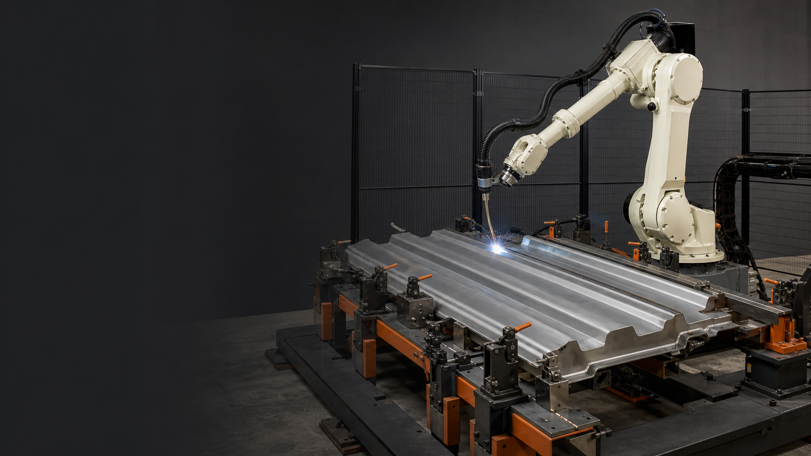
The first decision is whether the visible process and the proposed production claim describe the same system boundary. The supplied sequence was inspected frame by frame for observable equipment, workpiece motion, process state, and sequence changes. That observation supports only what can be seen; dimensions, settings, quality, timing, repeatability, safety performance, and production release still require project records and representative validation.
Observable sequence
- 00:00-00:06: a robot-mounted welding torch is positioned beside a formed or corrugated plate and a visible arc starts near a lower joint feature.
- 00:06-00:13: the arc, plume, and sparks remain visible while the torch position changes along the accessible joint area.
- 00:13-00:19: welding continues as the robot posture changes and the workpiece fixture remains stationary.
- 00:19-00:25: the arc ends and the torch moves away from the last visible welding position.
Evidence boundary: The footage does not prove a seam-tracking sensor, adaptive correction, seam length, material or thickness, welding procedure, thermal-distortion response, weld quality, defect reduction, cycle time, repeatability, customer acceptance, or site deployment.
Key takeaways
- Define plate thickness, profile range, joint geometry, seam location, and incoming variation before selecting a program concept.
- Establish repeatable fixture datums and a documented loading, clamping, and release sequence.
- Check torch posture, approach, exit, cable clearance, and surrounding interference for every path segment.
- Keep program and parameter changes inside approved welding-procedure and quality controls.
- Validate inspection, stop, restart, and recovery as part of the complete station cycle.
Define the part and joint range
Begin with current drawings, plate thickness, corrugation profile, overall dimensions, joint type, seam positions, material condition, and the expected variation of incoming assemblies. Mark which variants share a fixture and program and which require a controlled change. The specification should state the functional weld requirement and applicable acceptance route rather than rely on a visually continuous bead.
Separate measured inputs from assumptions. The cleared sequence shows a formed or corrugated plate and robotic welding activity, but it does not establish the supported part range, joint preparation, welding procedure, achieved quality, or production rate. Those conclusions require controlled project records.
Source basis: the project-input checklist and ISO 3834-1:2021 provide the input and documented-quality context. Neither is a result for the illustrated cell.
Establish a repeatable fixture datum
The fixture should locate the workpiece from defined datums and hold the joint condition required by the welding plan. Document loading orientation, clamp sequence, presence checks, released state, and prevention of a wrong or incomplete setup. Include tolerance from incoming parts, fixture wear, heat, tack condition, and operator loading where those factors can move the seam.
Review whether clamps obstruct the torch, shielding, observation, cleaning, or inspection. Also check access for maintenance and part removal. More restraint is not automatically better: the correct arrangement is the one validated with representative parts while keeping joint condition, distortion, and safe recovery inside the agreed window.
Source basis: the original WELD decision model and project-input checklist identify fixture questions; they are planning aids, not measured fixture evidence.
Verify every torch path and interface
For every seam segment, review the start and end point, approach and exit, torch angle, process-specific setup, robot posture, cable routing, fixture clearance, and access for service. If a positioner or external axis is used, include its coordinated sequence, payload and inertia limits, cable envelope, interlocks, and recovery position.
Path correction should be claimed only when the sensing and control method is identified and validated. The source sequence does not visibly prove a seam-tracking sensor. This article therefore treats sensing as a design option to be selected from the real joint variation and acceptance requirement, not as an installed capability.
Source basis: the WELD path-access model and the frozen timestamp observation. The observation proves visible torch motion and welding activity only; it does not prove seam tracking or adaptive correction.
Control procedure and program changes
Connect the robot program, welding settings, consumable condition, joint and material range, and applicable welding documentation by revision. Define who may change each value, how the change is recorded, the permitted adjustment window, and what first-piece or broader revalidation follows.
ISO 3834-1:2021 provides criteria for selecting quality requirements for fusion welding, while ISO 3834-6:2024 provides implementation guidance for the ISO 3834 series. They support a documented quality approach; they do not certify a particular cell or replace the governing welding code, procedure qualification, personnel responsibilities, or project acceptance plan.
Source basis: ISO 3834-1:2021, ISO 3834-6:2024, and the version-control fields in the project-input checklist.
Measure cycle, inspection, and recovery together
Break the station cycle into loading, locating, clamping, program selection, welding, any interpass or cleaning work, inspection, unloading, and interface waits. Record observed time by step under defined conditions and connect it to accepted-part evidence. Robot motion or arc-on time alone is not the station cycle.
Test controlled responses to incomplete clamping, wrong program selection, process interruption, consumable attention, inspection rejection, and restart. Recovery should preserve a known workpiece, program, joint, and inspection state so an interrupted weld is not silently treated as complete.
Source basis: the project-input checklist defines complete-cycle and recovery records; OSHA robotics guidance supplies the public safety context. Project fault tests remain required.
Release with representative welding evidence
Use representative part variants and joint conditions to verify loading, fixture repeatability, dry-run clearance, recipe recall, arc start and stop, full path coverage, inspection, and unloading. Record the applicable drawing and procedure revisions, material and consumables, program, fixture state, deviations, interventions, inspection method, and disposition.
A repeatable demonstration is still not a universal guarantee. Define release limits and change triggers for the part, joint, fixture, tool center point, consumables, welding settings, software, connected axes, and inspection plan. Retest the affected evidence after an approved change.
Source basis: the project-input checklist plus ISO 3834-1:2021 and ISO 3834-6:2024. Release still depends on the governing project records and acceptance plan.
Compare fixed paths, pre-weld sensing, and real-time adaptation
A fixture-controlled fixed path is the simplest concept when incoming parts and joint position remain inside a proven window. It minimizes sensing and correction complexity, but transfers more responsibility to upstream forming, fit-up, tacking, and fixture repeatability. Pre-weld offset sensing can locate selected features before welding and shift or rebuild a path within a validated range; it adds a sensing step and needs rules for confidence, out-of-range results, and recovery.
Real-time seam adaptation can respond during welding when the actual joint and process justify it. The selected sensor, process compatibility, field of view or signal quality, correction limits, filtering, latency, loss response, and acceptance evidence must all be specified. It is not automatically superior: reflective surfaces, arc conditions, geometry, access, contamination, or fast variation can restrict a method. Compare the three concepts with the same part family, joint variation, quality requirement, cycle definition, maintenance scope, and fault response. The correct choice is the least complex control method that keeps representative joints inside the approved welding and inspection window.
Source basis: the original WELD model and project-input checklist structure this comparison. It is an engineering planning framework, not a comparison dataset or proof that any sensing option is installed.
Build a repeatable station evidence record
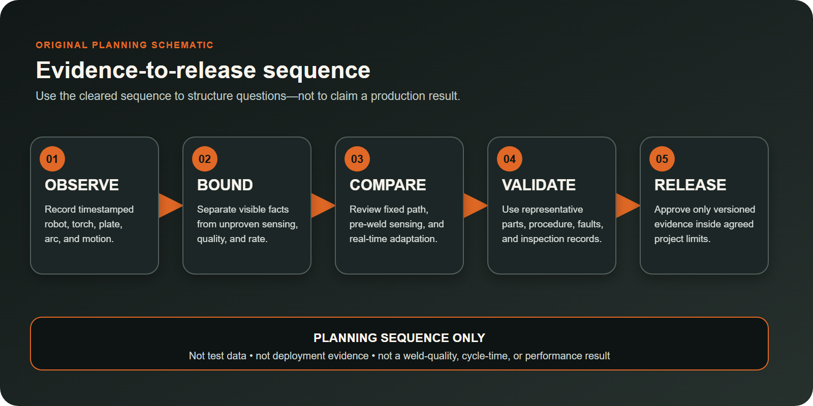
For each trial, retain the part and drawing revision, material and joint condition, fixture and clamp state, robot program, welding-document reference, consumable condition, process settings, tool calibration, start and stop locations, alarms, interventions, inspection method, result, and disposition. Time records should identify the boundaries of each station step rather than report one unexplained number.
Re-run the affected checks after fixture adjustment, torch or consumable changes, a program or procedure revision, connected-axis work, or a product variant that moves the joint outside the prior evidence. This record allows a team to distinguish fixture variation, access limits, process instability, inspection failure, and recovery loss instead of treating every problem as a robot-path issue.
Source basis: the project-input checklist defines the record fields and change triggers; the ISO 3834 references provide documented-quality context without certifying this application.
Decision table
| Decision area | Evidence to verify | Risk if unclear |
|---|---|---|
| Part range | Drawings, thickness, profile, joints, seams, and variation are versioned | Program is applied outside its validated range |
| Fixture | Datums, clamp sequence, presence checks, and clearances are proven | Joint condition varies between cycles |
| Path control | Each segment and any sensing method have a defined operating window | Collision, missed joint, or unsupported correction claim |
| Procedure | Programs and settings are tied to controlled welding documents | Uncontrolled parameter drift |
| Cycle and recovery | Full-cycle timing, inspection, stops, restart, and disposition are recorded | Incomplete welds or misleading rate assumptions |
Citable statements
Citable statement 1: A repeatable robotic weld path begins with a repeatable workpiece and fixture datum.
Source basis: WELD fixture-datum model and project-input checklist; see the downloadable original assets in this article.
Citable statement 2: Torch access should be checked segment by segment, including approach, exit, posture, cable clearance, and surrounding interference.
Source basis: WELD path-access model plus the timestamped frame-observation boundary.
Citable statement 3: Robot travel time is only one component of a welding station cycle; loading, clamping, process, inspection, and recovery also belong in the measurement.
Source basis: Project-input checklist covering the complete accepted-part cycle.
Citable statement 4: An interrupted weld cycle should return to a known workpiece, program, joint, and inspection state before production resumes.
Source basis: Project-input recovery row and the ISO 3834 documented-quality context.
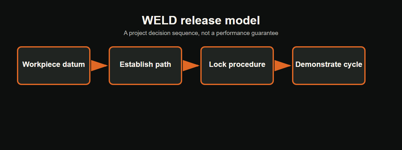
The WELD review model
EVST uses the WELD model as a planning aid for early application review. It organizes the evidence a project team would request before concept selection; it is not a performance guarantee or a substitute for project-specific trials and risk assessment.
- W — Workpiece and fixture: parts, joints, datums, clamps, and loading sequence.
- E — Establish the path: each seam segment, posture, clearance, sensing option, and coordinated motion.
- L — Lock procedure controls: programs, parameters, consumables, documents, and change authority.
- D — Demonstrate the station: full cycle, inspection, interruptions, recovery, and acceptance.
Download the project-input checklist.
Related resources
References
- ISO 3834-1:2021 — Quality requirements for fusion welding, Part 1
- ISO 3834-6:2024 — Guidelines on implementing the ISO 3834 series
- OSHA — Robotics standards and consensus guidance
Who prepared this guide, how, and why
- Author: EVST Editorial Team, an organization-level byline.
- Technical scope: EVST Technical Content Review, an organization-level review function.
- Method: Frame-by-frame observation of the cleared 25.23-second process sequence, followed by a decision model and project-input checklist. The method records visible sequence evidence separately from engineering requirements and does not convert footage into a performance or deployment claim.
- Why: This guide was written to help welding-cell buyers separate visible robot motion from the fixture, path-control, procedure, inspection, and recovery evidence required for a production decision.
- Policies: Editorial policy · Corrections policy · Terms of use · Privacy policy
Frequently asked questions
What inputs are needed for an initial corrugated plate welding review?
Provide current drawings, material and thickness, corrugation profiles, joint and seam locations, fit-up condition, welding documentation, fixture concept, production variants, target cycle, inspection method, layout, and interface requirements.
Does a successful visible weld path prove seam-tracking capability?
No. A seam-tracking claim requires identification and validation of the sensing, correction, control, supported joint conditions, loss response, and acceptance method. The footage used here does not visibly prove such a sensor.
When should a welding program be revalidated?
Define triggers around changes to the part or joint range, fixture datum, torch or consumables, robot path, process parameters, welding documentation, external axes, inspection plan, or relevant software and controls.
Next-step project inputs
Start with the corrugated-plate variant most likely to challenge torch access or joint location. Provide its profile and thickness, seam map and fit-up range, fixture datums and clamp sequence, applicable welding procedure, accessible inspection points, planned variants, and accepted-part cycle definition. A first-pass engineering review can use those inputs to screen whether a fixed path is sufficient or whether pre-weld sensing or real-time correction should enter representative trials. Final release still depends on project-specific welding, safety, inspection, and recovery evidence.