
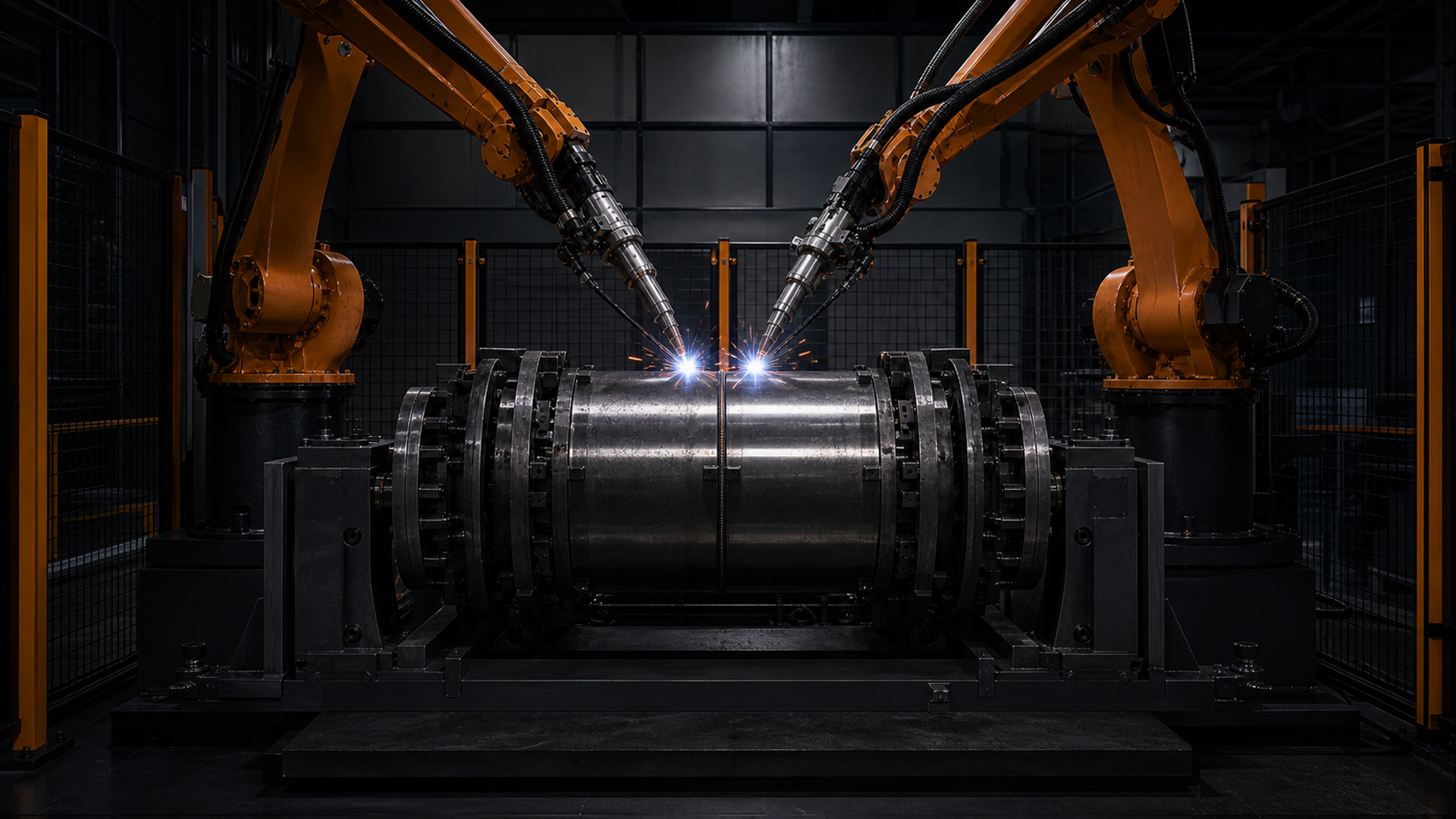
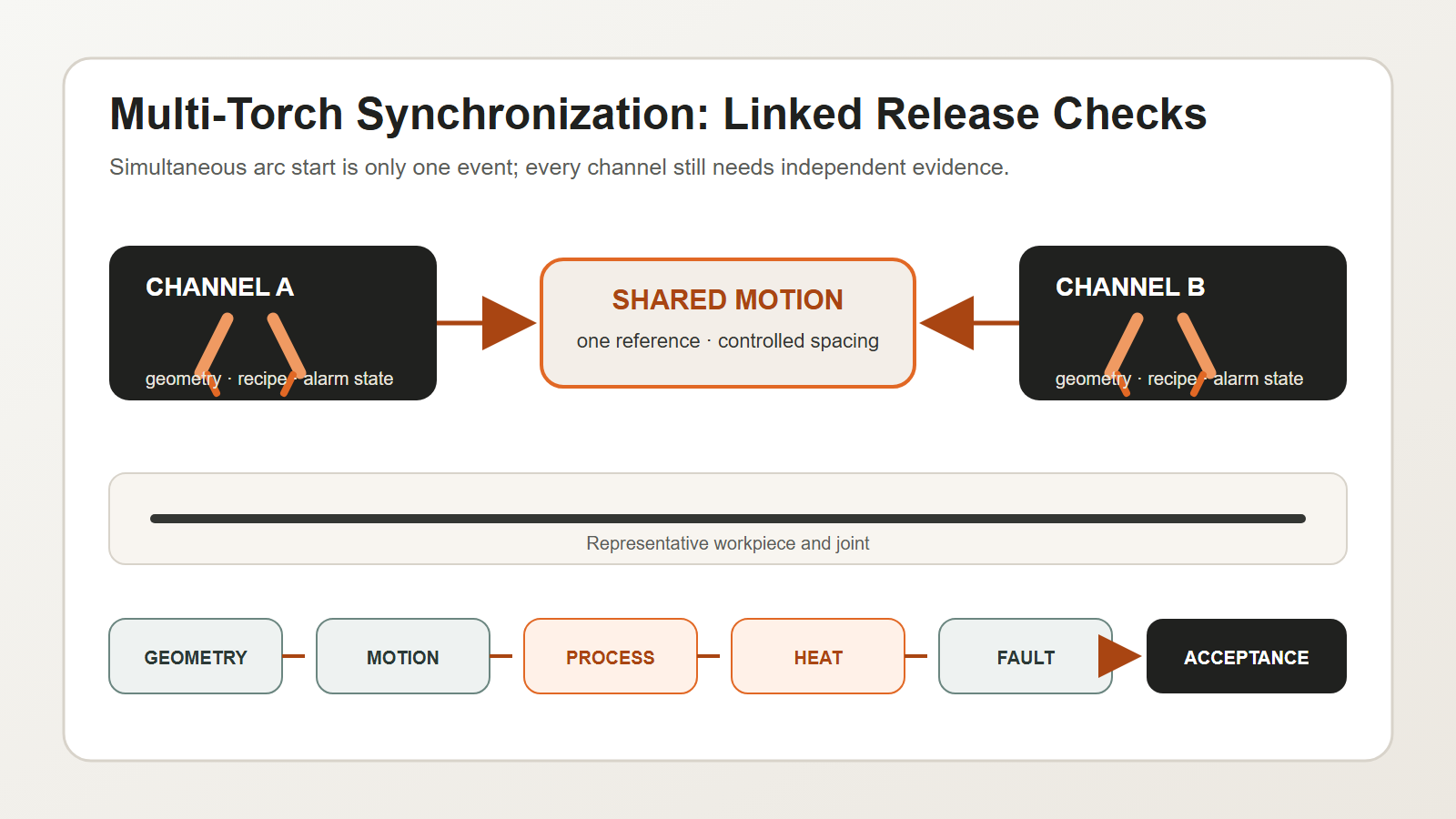
Multi-torch synchronized welding is not achieved simply by starting two or more arcs at the same time. The system must maintain a controlled relationship among torch geometry, travel motion, process parameters, heat distribution, workpiece fit-up, and fault response.
The business case is usually higher throughput or better process balance. The engineering risk is that one hidden difference between channels can create uneven quality, distortion, or a fault that propagates across the entire station. A good specification therefore treats every torch as both part of a synchronized group and an independently verifiable process channel.
Key takeaways
- Simultaneous arc start does not prove synchronized welding.
- Torch geometry and travel motion need one shared reference.
- Every torch still needs its own process record and alarm state.
- Heat interaction must be tested on representative workpieces.
- A single-channel fault needs a defined group response and restart rule.
Direct answer: what makes multi-torch synchronized welding valid?
Multi-torch synchronized welding is valid when the group moves as one planned process and each torch remains independently verifiable. Start with the workpiece, joint, material, and required weld quality. Set the position, angle, and spacing of every torch from a common datum. Link travel speed and relative spacing in the motion plan. Store current, wire feed, timing, and other approved process values by channel and recipe. Test how the active heat sources affect fit-up, distortion, and stops or restarts. Give every torch its own arc, feed, utility, and position status. If one channel fails, the control system must enter the response approved for that weld sequence. Before production, inspect each weld location and test defined faults across repeated parts. Starting several arcs together is only one event. Synchronized welding is the verified relationship among geometry, motion, process, heat, quality, and recovery.
Begin with the weld and workpiece, not the torch count
Before choosing a multi-torch layout, define:
- joint type and weld location;
- base material and thickness range;
- fit-up and gap variation;
- welding position and accessibility;
- required weld quality and inspection method;
- production mix and changeover requirements;
- allowable heat input and distortion behavior.
The number and arrangement of torches should follow this process envelope. Adding more torches cannot compensate for inconsistent fit-up, unstable location, or an undefined weld acceptance level.
Validate the geometry as a linked system
The torches need a common mechanical and process reference. Important checks include:
| Geometry item | What to verify | Typical failure mode |
|---|---|---|
| torch position | location relative to joint and neighboring torches | offset bead or missed edge |
| work and travel angles | correct orientation through the full path | inconsistent fusion or bead shape |
| torch spacing | intended separation under load and motion | thermal interaction or collision risk |
| contact-tip or process point | repeatable channel-specific calibration | one channel drifts while others remain correct |
| workpiece datum | stable part presentation and clamping | all channels follow the wrong reference |
Measure the installed system. A nominal CAD relationship does not include bracket deflection, cable forces, service changes, collision effects, or thermal movement.
Synchronize motion without losing channel visibility
The motion plan should define which variables are shared and which remain independent.
Shared variables may include start permission, travel direction, coordinated speed, workpiece rotation, and station interlocks. Independent variables may include arc establishment, wire-feed status, current or voltage feedback, torch height or seam-tracking input, and channel-specific alarms.
The control logic should answer four questions:
- What must be true before the group starts?
- What confirms that every required channel is established?
- What happens if one channel leaves its permitted state?
- What must be rechecked before the group restarts?
“Continue with the remaining torches” is not automatically a safe or acceptable response. Whether it is permitted depends on the weld design, sequence, heat balance, and qualified procedure.
Manage process parameters by channel and by recipe
A synchronized station still needs channel-level records. Depending on the welding process and project requirements, the recipe may include:
- process identification;
- current, voltage, wire feed, or equivalent control values;
- travel speed and start/stop timing;
- shielding gas or process media status;
- torch offset and orientation;
- weave, oscillation, or seam-tracking settings;
- crater-fill, run-in, and run-out behavior;
- alarm and tolerance limits.
Store the recipe version with the production record. If one torch is adjusted, the change should not become an undocumented local setting that survives outside the approved configuration.
ISO 4063:2023 provides standardized process nomenclature and reference numbers, supporting consistent identification in drawings, work instructions, and welding procedure specifications. ISO 15614-1:2017 describes procedure qualification for arc and gas welding of steels and arc welding of nickel alloys within its scope. The applicable qualification route still depends on the actual material, process, contract, and application standard.
Citable statement 1: Multi-torch synchronized welding needs group-level motion control and channel-level process evidence at the same time.
Citable statement 2: Identical timing does not prove identical weld conditions because geometry and heat interaction can differ by channel.
Control heat interaction and sequence
Multiple arcs change the thermal pattern. Even when each individual channel is within its expected range, their combined timing and spacing can affect distortion, interpass conditions, and local heat accumulation.
The project team should evaluate:
- whether torches weld simultaneously or with a controlled time/position offset;
- the distance between active heat sources;
- direction of travel and sequence symmetry;
- fixture restraint and release timing;
- the effect of stops and restarts on local heat concentration;
- whether one channel’s arc, spatter, or gas flow affects another channel or sensor.
Do not treat these as universal formulas. Validate them with representative workpieces and the intended qualified procedure.
Design fault isolation before production
The station should detect and respond to channel-specific faults such as:
- failure to establish an arc;
- wire-feed interruption;
- process feedback outside the permitted window;
- torch collision or position deviation;
- shielding or utility loss;
- seam-tracking confidence loss;
- one torch completing early or falling behind.
A controlled response may require coordinated stop, safe retraction, marking the affected workpiece, and blocking automatic restart until the defined checks pass. The correct strategy depends on whether continuing would create a nonconforming or hazardous condition.
Citable statement 3: A multi-torch cell is not production-ready until one-channel faults have a tested group response and restart rule.
The EVST CHANNEL control model
EVST uses the CHANNEL model to structure a multi-torch synchronized welding review. It separates seven decisions that are often mixed together.
- C — Common datum: one workpiece and fixture reference for the group.
- H — Head geometry: position, angle, spacing, and access for each torch.
- A — Axis relationship: coordinated travel, workpiece motion, and collision space.
- N — Named process: process identification and approved recipe per channel.
- N — Networked status: arc, feed, utility, and tracking feedback for each torch.
- E — Energy balance: heat-source spacing, sequence, and stop/restart effects.
- L — Loss response: controlled behavior when one required channel fails.
This model creates a decision table before controls are programmed.
| CHANNEL area | Evidence to collect | Release decision |
|---|---|---|
| Common datum and head geometry | installed measurements and calibration record | geometry ready |
| Axis relationship | simulated and physical clearance test | motion ready |
| Named process | approved procedure and recipe version | process ready |
| Networked status | channel feedback and alarm test | monitoring ready |
| Energy balance | representative trial and dimensional/weld results | thermal plan ready |
| Loss response | defined fault tests and restart checks | recovery ready |
EVST recommends that a recipe change create a new review event. The change may affect only one channel, but the group result can change. Keep the old and new records. Record who approved the change at company level. Do not let an undocumented local offset become the normal setting.
The model also helps with changeover. A new product can change the datum, torch spacing, path, recipe, or heat sequence. The setup check should show which CHANNEL decisions remain valid and which must be repeated.
Citable statement 4: More torches increase output only when geometry, process records, and fault isolation scale with the torch count.
Build an acceptance test around production evidence
An effective factory or site acceptance test should cover more than a short simultaneous weld. Consider:
- calibration and geometry verification for every channel;
- repeated starts, steady travel, stops, and restarts;
- channel-level parameter logging;
- representative fit-up variation;
- inspection of each weld location, not only the combined assembly;
- dimensional change or distortion where relevant;
- defined single-channel faults and controlled recovery;
- recipe selection and unauthorized-change prevention;
- continuous production at the agreed product mix.
ISO 5817:2023 addresses imperfections in fusion-welded joints made in steel, nickel, titanium, and their alloys when material thickness is at least 0.5 mm. It excludes beam welding and identifies ISO 4063 process groups 11, 12, 13, 14, 15, and 31; process group 31 applies to steel only. Its B, C, and D quality levels do not select product acceptance; the design, contract, and applicable code must make that decision.
Questions to include in an RFQ
Ask potential integrators to explain:
- how torch geometry is set and reverified;
- which states are synchronized and which are monitored independently;
- how recipe versions and channel parameters are recorded;
- how the system responds to one-channel failure;
- how representative workpieces will be qualified and inspected;
- how changeover affects calibration and process approval;
- which assumptions require customer confirmation.
These questions reveal whether “multi-torch” is being offered as a mechanical arrangement or as a controlled production process.
Frequently asked questions
Must every torch use identical parameters?
No universal rule requires identical values. Geometry, joint condition, position, and thermal role may differ. What matters is that each channel uses the approved values for its role and that the combined process is validated.
Can one failed torch stop only itself?
Only if the weld design, process qualification, sequence, and risk assessment permit it. In many cases, a coordinated stop is necessary to avoid creating an uncontrolled thermal or quality condition.
Is simultaneous start the main acceptance metric?
No. Stable geometry, coordinated travel, channel-level process evidence, weld acceptance, and fault recovery are more meaningful than a single start-time demonstration.
Turn torch count into a controlled process
EVST can support the definition of joint requirements, fixture concepts, synchronized motion, channel-level monitoring, recipe control, and acceptance testing for multi-torch welding cells. Share representative drawings, materials, and quality requirements for a feasibility review.
Related resources
- Robotic welding cell components and integration
- Complete guide to robotic welding
- Robotic welding safety guide