By the EVST Editorial Team · Last updated: June 9, 2026
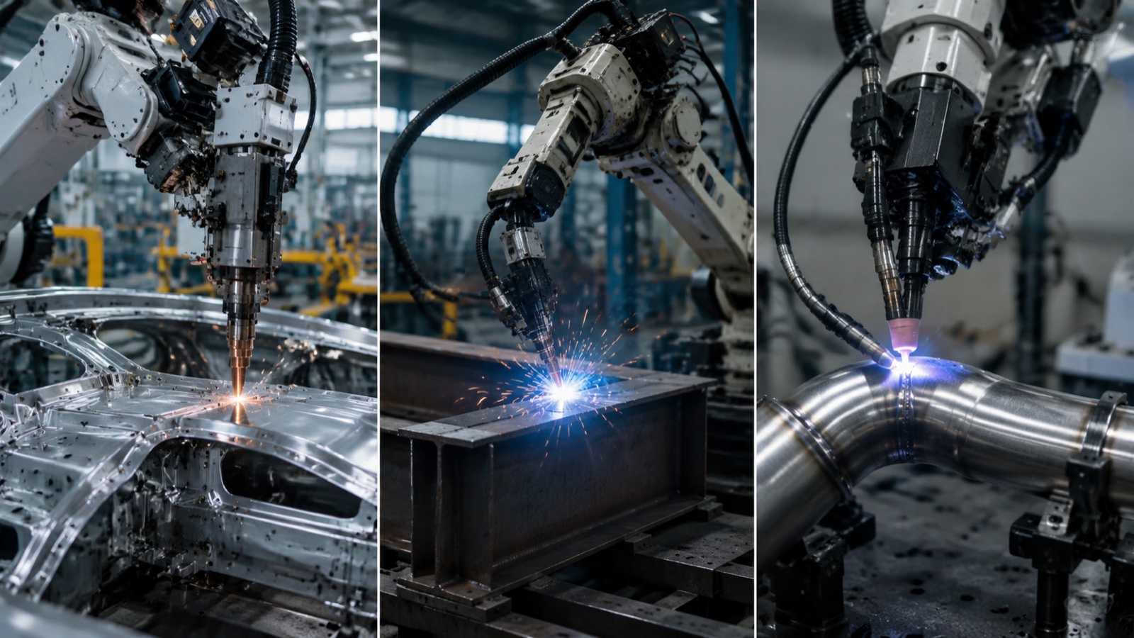
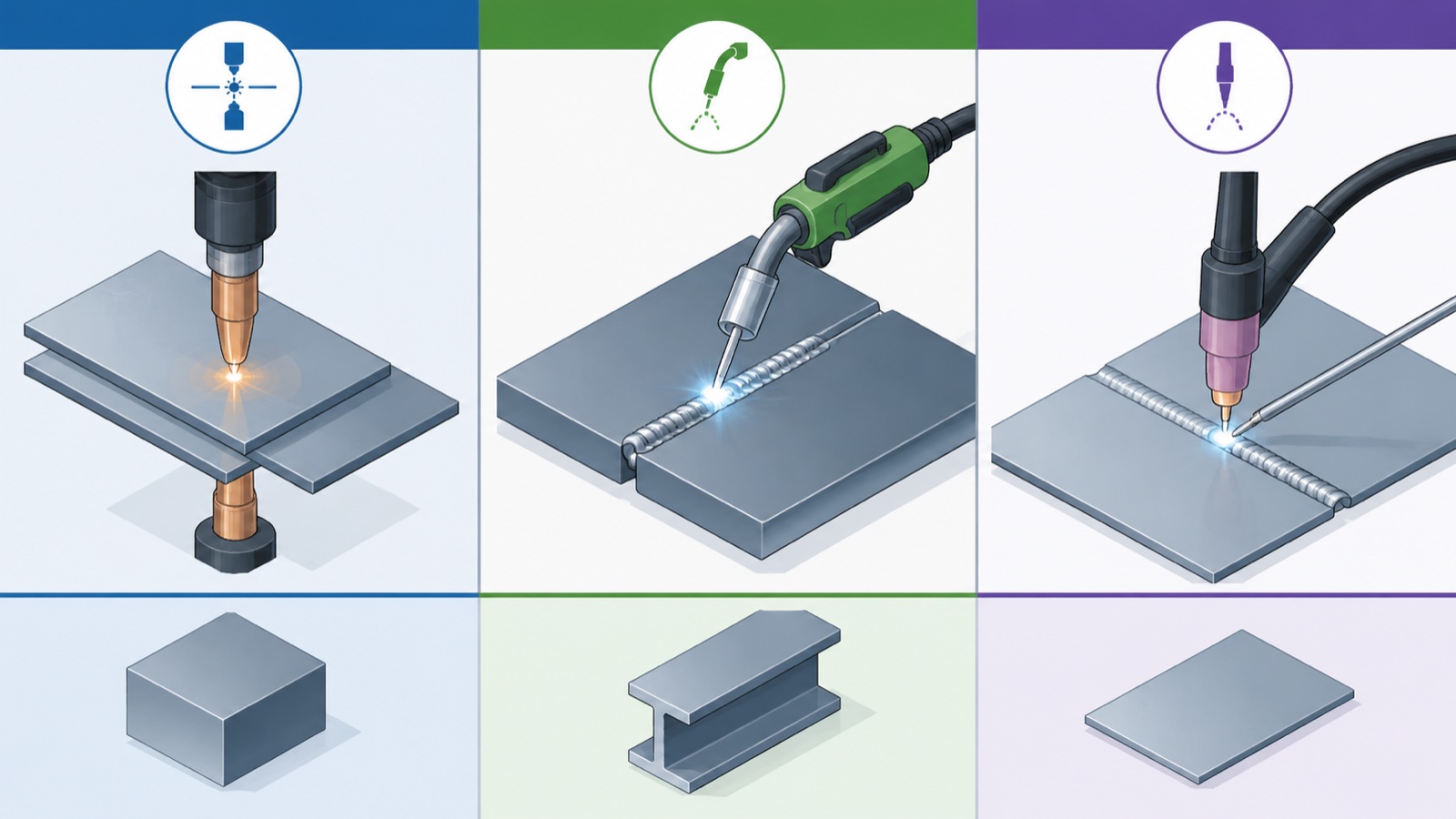
Spot welding joins overlapping sheet metal up to 3 mm thick, used heavily in automotive body-in-white. MIG (GMAW) handles high-deposition arc welding on 1 to 25 mm structural steel and aluminum. TIG (GTAW) covers precision arc welding on thin or exotic materials (stainless, aluminum, titanium) under 6 mm. Each maps to a distinct robot payload class, cycle time, and quality regime. Selection follows the part, not the process.
Three Processes, Three Production Models
Spot, MIG, and TIG are not three flavors of the same operation. They are three different production models that happen to share the word “welding.” A spot welding robot picks point welds on overlapping sheet. A MIG robot lays continuous beads at high deposition. A TIG robot lays narrow, controlled beads where the metallurgy matters more than the speed. The robot payload, the power source, the cell layout, and even the operator skill profile differ across the three.
For a broader view of how 6-axis welding robots fit into heavy industry, see the EVST guide to welding robots for MIG, TIG, and spot processes. This article zooms into the process comparison itself.
Process Comparison Table
| Attribute | Spot (RSW) | MIG (GMAW) | TIG (GTAW) |
|---|---|---|---|
| How the bond is made | Resistance heat from current through two electrodes clamping the sheets | Continuous arc with consumable wire as filler | Continuous arc from non-consumable tungsten electrode, filler added separately |
| Filler material | None | Consumable wire (solid or flux-cored) | Separate rod, fed by hand or cold/hot wire feeder |
| Shielding | None (no arc) | Inert/active gas (Ar, CO₂, Ar+CO₂ mixes) | Inert gas (Ar, Ar+He mixes) |
| Material range | Carbon steel, HSLA, some aluminum (challenging) | Carbon steel, stainless, aluminum, copper alloys | Stainless, aluminum, titanium, nickel alloys, exotic metals |
| Thickness range | 0.5 – 3 mm sheet pairs | 1 – 25 mm (multi-pass beyond) | 0.5 – 6 mm typical, can go thicker with multi-pass |
| Joint type | Lap (overlap) joints only | Butt, fillet, lap, T, edge — full range | Butt, fillet, lap, T — full range, especially groove welds |
| Deposition rate | N/A (point-by-point) | 1 – 10 kg/hr | 0.2 – 1 kg/hr |
| Cycle per joint | 0.5 – 2 seconds per spot | Seconds per linear cm | Slower, multi-pass for thick joints |
| Heat input | Very short, very localized pulse | Medium to high | Low to medium, highly controllable |
| Distortion risk | Low (small heat-affected zone) | Medium to high, especially on long seams | Low (controlled heat input) |
| Typical robot payload | 165 – 350 kg (gun + arm) | 6 – 20 kg (torch) | 6 – 12 kg (torch) |
| Operator skill required | Lower (point operation) | Medium (parameter setup, gas control) | Higher (parameter setup, dynamic control, tungsten dressing) |
| Suited to | Body-in-white, white goods, electrical enclosures | Structural steel, construction equipment, heavy fabrication | Pressure vessels, stainless food/pharma, aerospace, thin gauge |
When Each Process Is the Right Choice
Choose spot welding when
The part is two or more sheets of carbon steel or HSLA, 0.5 to 3 mm each, overlapping at the joint. The volume justifies tandem or multi-station robot lines. The quality requirement is per-spot strength and traceability rather than continuous-seam appearance. Examples: body-in-white, washing machine drums, refrigerator cabinets, transformer enclosures, control panels.
According to industry observations, a single automotive body-in-white shell can take 200 to 400 spot welds across 4,000 to 5,000 individual sheet contact points. The economic case for robotization is built on raw cycle count, not weld complexity.
Choose MIG (GMAW) when
The part is 1 to 25 mm steel or aluminum with linear seams measurable in centimeters or meters. Deposition rate matters. Joint geometry varies enough that an arc-based process can absorb minor fit-up variation. Examples: excavator booms, dump truck beds, tractor chassis, structural beam fabrication, pipe spool work, agricultural implements, ship blocks (with linear track for reach).
MIG covers roughly 70 percent of arc welding robot installations in heavy industry because it matches the most common production model: structural steel weldments, mid-to-thick plate, long seams, throughput-driven economics.
Choose TIG (GTAW) when
The part is stainless steel, aluminum, titanium, or a nickel alloy in 0.5 to 6 mm range. The weld will be inspected under code (ASME Section IX, ISO 15614, AWS D17 for aerospace). The metallurgical integrity of the heat-affected zone determines pass or fail. Examples: pressure vessels, heat exchangers, sanitary stainless piping, aluminum boat hulls, aerospace airframe sub-assemblies, nuclear components.
TIG is slower and more expensive per linear meter than MIG, but it is the only choice when the part will be inspected by radiography or ultrasonic methods and the metallurgy is unforgiving.
Common Mis-Selections
Three patterns appear repeatedly in heavy industry welding cell projects that underperform.
- Specifying TIG when MIG would do. A buyer chooses TIG because the welds “look prettier” or because the supplier’s reference list features stainless work. If the part is carbon steel and inspection is visual only, MIG covers the requirement at higher throughput and lower consumable cost.
- Forcing spot welding on parts above 3 mm. Spot weld strength drops off rapidly above 3 mm per sheet because resistance heating cannot maintain a consistent weld nugget through thicker stack-ups. Most parts above 3 mm should use projection welding, MIG, or fastener joining instead.
- Single-process specification for multi-process work. A part that has thin-gauge stainless covers and thick steel structural ribs will benefit from a hybrid cell (TIG on the covers, MIG on the ribs). Forcing one process to serve both invariably compromises one side.
Robot Payload Matching by Process
The process determines the payload class. The payload class determines the robot model. Specifying robot first and process second is the most common cause of stranded capacity.
| Process | Robot payload range | What the payload carries |
|---|---|---|
| MIG light | 6 – 8 kg | Air-cooled torch, simple wire feed, thin-gauge work |
| MIG standard | 12 – 20 kg | Water-cooled torch, wire feeder, optional seam tracking sensor |
| MIG heavy / narrow-gap | 25 – 50 kg | Multi-process welding head, narrow-gap torch, dual-wire systems |
| TIG standard | 6 – 12 kg | Torch with cold-wire feeder, AVC sensor, weld monitoring |
| TIG hot-wire / multi-process | 12 – 20 kg | Hot-wire TIG head, integrated camera, weld pool monitor |
| Spot light (white goods) | 50 – 165 kg | Pneumatic spot gun, weld controller |
| Spot automotive standard | 165 – 250 kg | Servo spot gun, transformer, weld controller with logging |
| Spot heavy / multi-tool | 350 – 800 kg | Large servo gun, tool changer, multi-process heads |
Cell-Level Implications
The process choice ripples through every other cell decision.
Positioner: arc processes (MIG, TIG) benefit massively from a positioner because welding in the flat position is faster and lower-defect. Spot welding rarely needs a positioner because the gun reaches in and clamps; the workpiece is held in a body-in-white fixture instead.
Fume extraction: MIG produces the heaviest fume load and dictates the most aggressive extraction. TIG produces less fume but still requires extraction. Spot welding produces almost no fume (no arc) but does produce noise and electrode wear debris.
Safety enclosure: arc processes require opaque welding curtains to block arc flash. Spot cells can use light curtains or mat-protected zones because there is no arc to shield workers from.
Programming model: spot weld programs are essentially a list of weld coordinates with parameters per spot. Arc weld programs are continuous-path trajectories with weave patterns, lead-in / lead-out moves, and arc-on / arc-off events. Programming time per part is typically 2 to 5× higher for arc than for spot.
Consumables: spot welding consumables are electrode caps (replaceable, hundreds to thousands of welds per cap). MIG consumes wire (kg per shift), contact tips, gas diffusers, and shielding gas. TIG consumes tungsten electrodes (low rate), filler wire, and shielding gas.
According to industry observations, the consumable cost gap between TIG and MIG is roughly 3 to 5× for a comparable joint length, which compounds over a year of three-shift operation and is one reason MIG dominates volume structural work even when TIG could deliver the joint metallurgically.
Selection Workflow in Practice
In practice, when EVST application engineers help a buyer scope a welding cell, the conversation runs in this order:
- What is the part? Material, thickness, joint type, expected weld count per part.
- What is the quality regime? Visual only, dye-penetrant, radiography, ultrasonic, weld procedure code.
- What is the volume? Parts per shift, shifts per day, days per week.
- What is the cycle time target?
- From the above, the process narrows to one or sometimes a hybrid of two.
- Then the payload class follows from the process and torch / gun selection.
- Then the cell components (positioner, track, seam tracking) follow from the payload and part geometry.
Skipping steps 1 through 4 and starting at “which robot” is the most common reason cells underdeliver. For cell-level specification details after the process is locked, see the EVST product-site guide on welding robot cell selection.
Frequently Asked Questions
Can one robot do MIG and TIG with a tool changer?
Yes, but uncommon in production. The cycle-time penalty of swapping torches and re-routing gas/wire usually outweighs the flexibility gain. Two robots, one per process, is the more common solution when both processes are needed at volume.
Why is spot welding faster per weld than MIG?
Spot welding makes a single point bond in 0.5 to 2 seconds, including the clamp-weld-release cycle. MIG has to traverse the seam at deposition-limited speed, plus arc strike and crater fill. Per joint, spot is faster; per linear length, MIG is the only option.
What materials cannot be welded with any of these three processes?
Highly reactive metals (magnesium with thick cross-section, beryllium), cast iron in many configurations, and dissimilar metal combinations with widely different melting points often require alternative processes (laser, friction stir, electron beam) or specialized procedures outside the standard MIG/TIG/spot envelope.
Is laser welding replacing MIG and TIG?
Laser welding is growing in automotive (especially for tailored blanks and battery enclosures) and in some thin-gauge stainless work, but has not displaced MIG or TIG in heavy industry. Capital cost, joint preparation tolerance, and material range are still constraints that favor arc processes for general fabrication.
How long does a process changeover take in a multi-process cell?
For a robot that switches between MIG and spot, tool-changer cycle plus re-zeroing typically takes 30 to 90 seconds. For a switch between MIG and TIG on the same arc cell, parameter program load and gas changeover takes 1 to 3 minutes. These are floor-time costs that should be factored into cycle-time models.
About the author: The EVST Editorial Team writes about industrial robotics and intelligent manufacturing for engineers and operations leaders evaluating automation projects. EVST (EVS TECH CO., LTD), founded in Chengdu in 2018, has delivered 600+ automation projects and ships to 100+ countries, with IATF 16949 automotive-grade certification and CE / SGS / TUV third-party certifications across the QJAR, XR, EVS, and EVSD product families.