
A circular interface on a long shaft assembly is governed by coupled geometry: support position affects axis location, axis variation changes torch angle, and the required weld region determines which access must remain open. The footage confirms an active arc at one visible plate-to-shaft or tube interface; it does not prove rotation or a complete circumferential weld. Ask EVST to review your application →
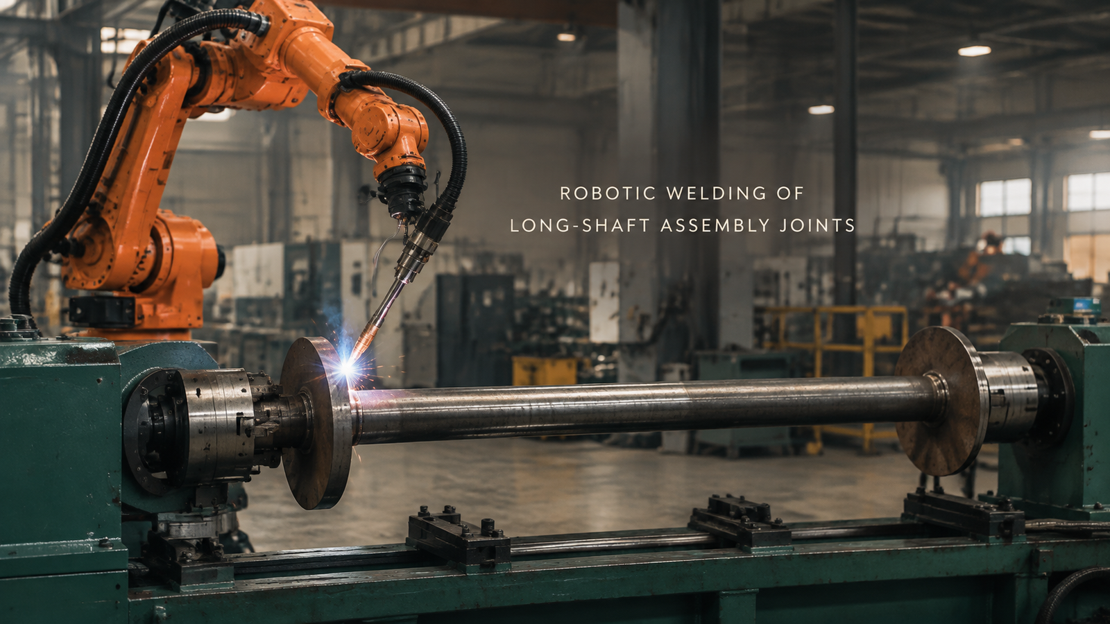
The close view turns support into a welding question
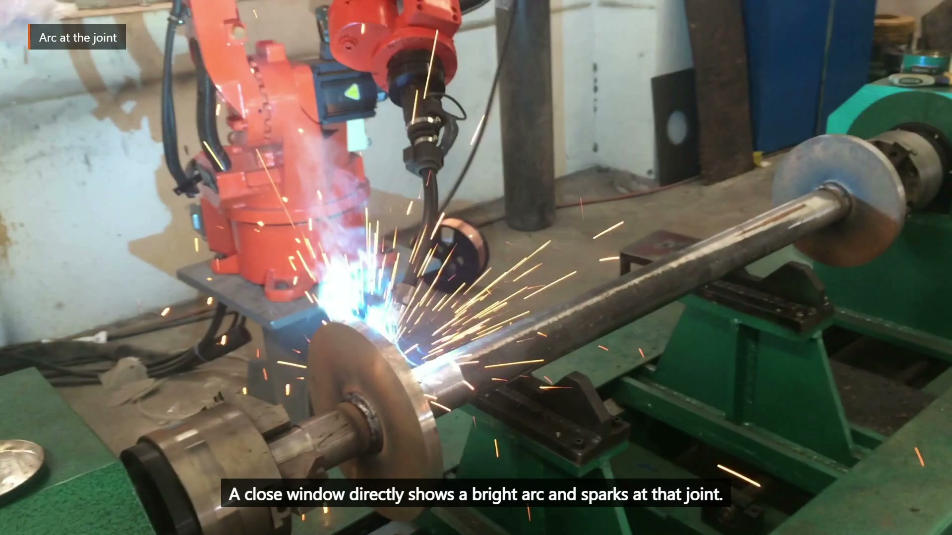
At 00:29.35, a bright arc and sparks are visible at one circular interface.
The near side may be open while the far side is hidden by the member, plate or support. A long assembly also magnifies small changes in sag, straightness and axial location. Supporting the member more firmly can improve joint location yet occupy the torch angle needed at the most restricted weld region. These are not separate fixture and robot questions.
The wide view shows the relationship among robot, long member, circular plates and green supports.
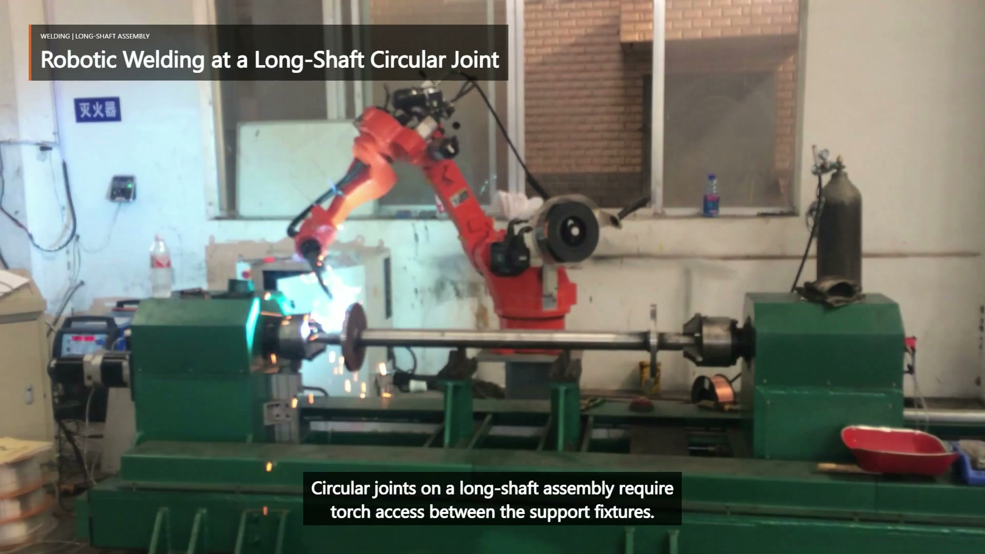
At 00:04.00, the robot works beside the supported long horizontal assembly.
Use the interaction table before choosing presentation
| Proposed change | Geometry to recheck | Acceptance evidence |
|---|---|---|
| Move or add a support | Sag, joint location and blocked torch space | Measured axis and interface position after clamping |
| Tighten axial location | Plate position and start/stop access | Full incoming tolerance range at the fixture |
| Change torch approach | Cable clearance, support interference and inspection view | Swept-envelope review at the hardest required region |
| Divide the required weld into segments | Permitted starts, stops, overlaps and reposition moves | Drawing, weld specification and inspection plan |
This review should start with the required joint extent. One visible arc cannot define whether the project needs a short segment, several regions or another requirement. Only then can support and access be evaluated against the correct target.
Compare two general presentation strategies in a trial
A fixed presentation is attractive when every required region remains reachable and the supports hold the axis within the allowed range. Its trial should challenge the longest assembly, greatest expected sag, plate-position variation and most obstructed torch angle.
If one presentation cannot expose all required regions, an adjusted presentation may be studied as a general engineering option. That option adds repeatability, control and re-location questions and must be validated; it is not evidence that the filmed assembly rotates. For either strategy, separate arc-on segments from repositioning and reserve inspection access.
Evaluate the worst weld region and worst incoming part together
Early evaluation is worthwhile when support hardware competes with torch access, long members sag, plate position varies, or the drawing demands an awkward angle. Bring the assembly drawing, required joint extents, weld symbols and acceptance criteria, length and straightness tolerances, plate-position and fit-up variation, proposed support and datum concept, torch and cable envelope, and representative parts.
The first trial should locate the axis after clamping, verify the most restricted required region, check permitted start and stop access, and inspect the assembly after release before output is estimated. Send these inputs for an EVST concept review → or email sales@evsrobot.com.
The footage confirms welding at one visible interface; final joint extent, tooling, controls and production acceptance depend on project validation.