
By EVST Editorial Team · Reviewed by EVST Editorial Team · Last updated September 24, 2026 · Editorial policy · Corrections policy · Terms
Bowl-shaped-part unloading should be designed around supported contact, release clearance, and a stable receiving surface. The footage shows an orange robot using a beam-style tool with several white contact positions near pale bowl-shaped parts inside open equipment, then moving toward an outside table. A concept review should test the full shape and surface range before assigning a production rate. Discuss the application with EVST.
The critical handoff happens before the robot moves away
The visible motion begins at an equipment opening. Several pale bowl or tray forms stand inside, while the robot presents a wide tool with multiple contact positions. That arrangement puts the first engineering question at the part-tool interface: can the tool establish support without concentrating force on a rim, touching a protected surface, or disturbing an adjacent part?
The footage shows contact and withdrawal relationships, but it does not establish material composition, forming method, vacuum level, breakage rate, or inspection outcome. Those become test inputs, not case results.
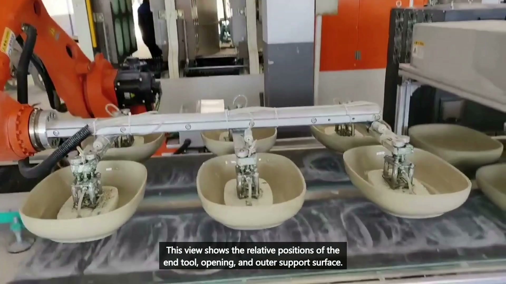
Final main video 00:35 — Multiple tool contact positions sit inside bowl-shaped parts on the outer support surface.
Build the trial around failure modes, not one clean lift
Representative trials should include the shallowest and deepest forms, the widest dimensional spread, surface dust or moisture expected in production, and parts that sit slightly off-center. Contact pressure or vacuum response should be measured with the actual tool and surface. If one contact point seals or loads differently from the others, the part can tilt during withdrawal even when the initial pickup looks acceptable.
| Trial stage | What to observe | Acceptance question |
|---|---|---|
| Approach | Rim, wall, and neighboring-part clearance | Does the tool arrive without side contact? |
| Pickup | Contact distribution and part movement | Is support established without visible shift or damage? |
| Withdrawal | Tool, part, and equipment-opening clearance | Can the held part leave through the full path? |
| Release | Landing support and tool retreat | Does the part remain stable after the tool clears? |
The outside table is part of the unloading system
An unloaded part is not complete merely because it has left the equipment. The receiving surface must support the actual base geometry and preserve any required orientation. Space is also needed for the tool to release and retreat without brushing the rim or neighboring parts.
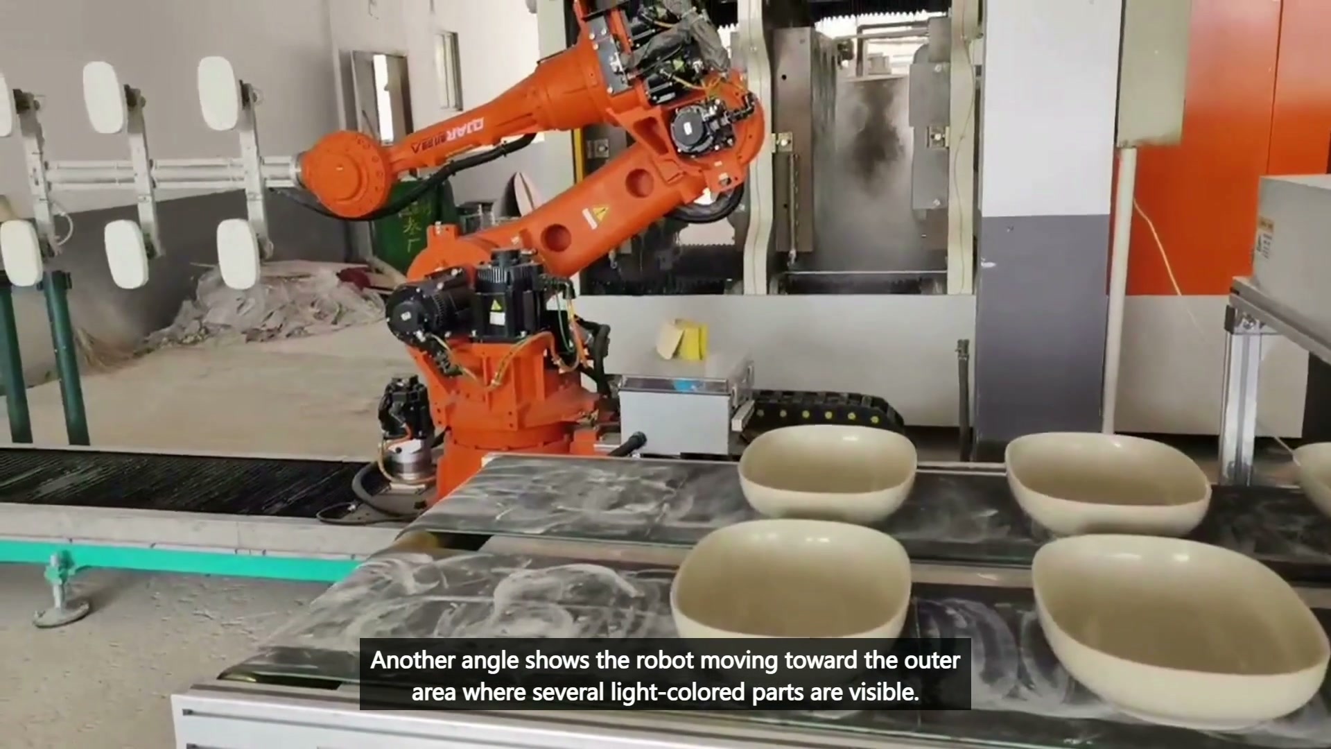
Final main video 00:43 — The robot is beside the equipment while several bowl-shaped parts sit on the outer support table.
For a multi-part tool, define what happens when one position is empty or fails to establish acceptable contact. The controls may stop, complete a reduced load, or place parts in a separate recovery location, depending on the process risk. That behavior should be agreed before cycle optimization.
A practical decision sequence
Start with drawings and real samples. Identify permitted and protected contact regions. Verify the equipment presents each part inside a repeatable envelope. Test pickup and withdrawal separately, then confirm placement and tool retreat. Only after those interfaces are stable should the team measure a complete sequence.
This order prevents robot speed from hiding presentation or tooling problems. It also produces a useful fault record: no part presented, incomplete contact, part shift, blocked exit, unstable landing, or occupied destination.
Questions buyers usually ask
Is vacuum always the right method for bowl-shaped parts?
No. Surface texture, porosity, geometry, contamination, allowable contact, and the required support area determine whether vacuum, compliant contact, or another tool is appropriate.
Should the robot carry several parts at once?
Only after the tool can support each position across the real part range and the equipment and receiving table provide enough clearance for the combined load.
What should the first trial prove?
It should prove repeatable presentation, supported pickup, clear withdrawal, stable placement, and a defined response to a missing or mispositioned part.
Inputs for an unloading study
- Part drawings, mass range, and representative samples
- Protected surfaces and permitted contact regions
- Equipment opening, internal obstacles, and release position
- Receiving-table support, spacing, and accumulation rules
- Output target, changeover range, and fault recovery needs
- Inspection criteria after pickup and release
Send the part drawings, samples, equipment interface, and output target to sales@evsrobot.com, or use the EVS International contact page. EVST can review tool contact, withdrawal clearance, receiving support, and the validation plan.
Visible footage supports the unloading and transfer discussion. Tool type, material properties, process parameters, cycle performance, and part acceptance require project validation.