
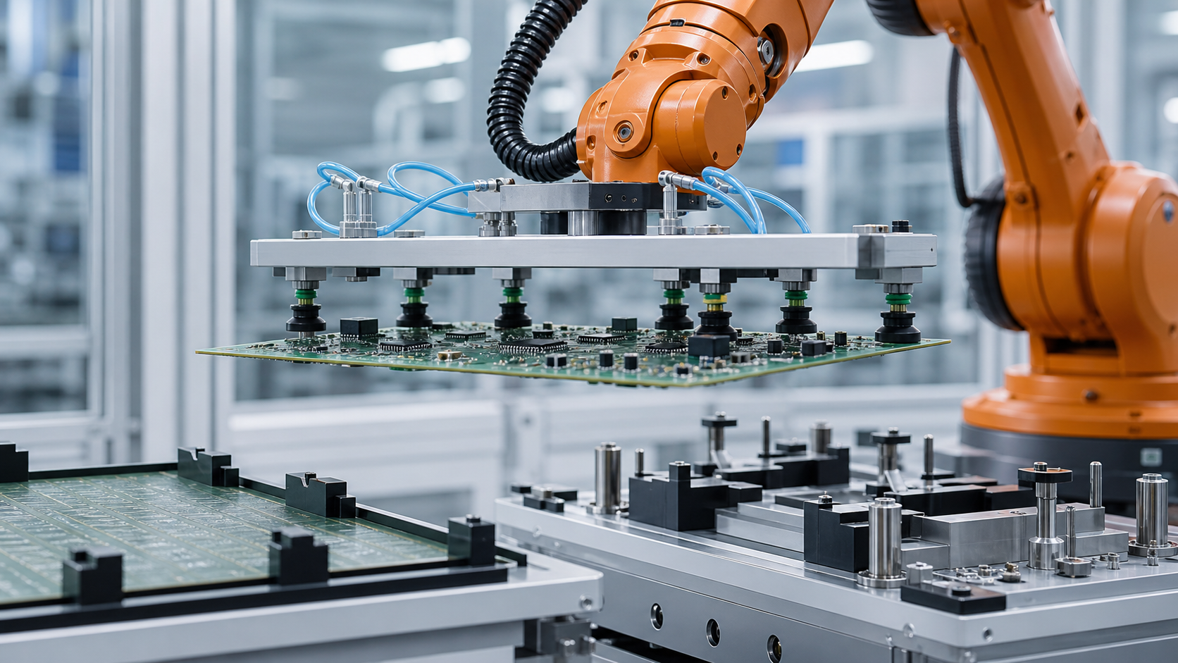
This guide is for manufacturing engineers, electronics-process owners, controls engineers, integrators, maintenance teams, and quality planners evaluating board-shaped workpiece transfer. EVST treats the board as a supported structural part with protected regions, not as a rigid rectangle that can be carried from its nominal center.
What an application view can—and cannot—show
The visible application shows a robot transferring a board-shaped workpiece with suction tooling. That action is useful for identifying engineering questions about support, contact, motion, and placement, but it does not reveal the design records or test results needed to validate the process.
The visible action does not establish the board drawing, material stack, allowable deflection, vacuum performance, contact pressure, motion limits, placement accuracy, product inspection outcome, repeated-cycle capability, environmental suitability, safety validation, compliance, or certification. EVST does not infer any of those results from a brief application view.
Define the board states before choosing contact points
A useful state model distinguishes how the board is supported before pickup, how it is held during transfer, and how it is located after placement. Incoming boards may rest on edge rails, a carrier, a flat nest, spacers, or temporary packaging. The intended pickup plane and accessible regions can change with each state.
Record top and bottom component envelopes, connector projections, tooling holes, panel rails, keep-out regions, fragile surfaces, labels that must remain readable, and any feature that may be used as a datum. If the board is part of a panel, note whether singulation occurs before or after the robotic step; the support behavior and allowable contact regions may be different.
Compare support and gripping concepts
| Concept | Useful starting condition | Evidence to validate | Assumption to avoid |
|---|---|---|---|
| Distributed vacuum contacts | Several compatible surface regions are available and local support can be spread across the board | Contact compatibility, zone response, seal variation, load sharing, partial-contact detection, and release | One pressure reading proves every cup is engaged |
| Edge or rail support | Board edges or panel rails are controlled and can carry the required transfer load | Edge variation, retention, corner clearance, orientation, and insertion or removal path | A nominal outline guarantees usable edge access |
| Mechanical frame or carrier | The product can travel on a controlled reusable support | Carrier datum, board-to-carrier relationship, retention, contamination, and downstream compatibility | A carrier removes the need to verify the board state |
| Hybrid support | One method establishes location while another distributes load or prevents loss | Responsibility of each contact, state detection, tolerance interaction, and release order | More contact devices automatically create more reliable evidence |

Create a contact and keep-out map
For every proposed contact, identify the physical region, surface finish, local stack, neighboring components, expected normal direction, and allowable sliding or rotation. The map should also show where the tooling frame, fittings, fasteners, and sensors may pass during approach. This prevents a clear cup location from hiding a collision elsewhere on the end effector.
Keep-out regions should include more than obvious tall components. Consider connectors, soldered features, test points, optical surfaces, coatings, labels, board edges, and areas needed by the destination fixture. Contact compatibility must be established by the product owner; a visually flat region is not automatically an approved gripping surface.
Trace the load path through the board and tool
The gripper carries its own frame, fittings, hoses, sensors, and the board. The design record should show how each load travels from the board through contact elements into the tool structure and robot flange. A wide tool may add rotational inertia even when its total mass is within a nominal payload value.
Validate more than static holding. Lift can reveal unequal pickup, rotation can change how gravity acts through the board, and deceleration can add relative motion or deflection. The route near fixtures and guarding must account for the actual swept volume of the board, not only the tool center point.
Use independent grip zones and interpretable feedback
When vacuum is used, grouping contacts into meaningful zones can make a partial pickup easier to diagnose. The zone design should correspond to board geometry and accepted contact states, not merely to convenient hose routing. Feedback should distinguish ready, uncertain, lost, and release states in a way the controller can act upon.
A common line may not reveal which contact is missing. If the application requires continued operation after one unavailable point, that condition needs a validated rule tied to the real support map and load test. Otherwise the controlled response is to hold or return the board rather than assume the remaining contacts are sufficient.
Separate pickup alignment from placement datum
The pickup location may be approximate while the destination requires a tighter mechanical datum. Decide whether the robot is expected to place directly onto locating pins, present the board to a compliant nest, hand it to an alignment mechanism, or use a carrier. Each option changes contact forces, approach direction, and the evidence for successful seating.
Do not make the tool fight the fixture. If the board remains rigidly constrained by the gripper while the nest tries to establish a different position, small mismatch can load the board or datum features. Sequence support, location, grip release, and final seating so ownership transfers intentionally.
Define placement as several confirmed states
“Robot at place position” is only one state. The system may need to confirm destination available, board presented, datum engaged, board supported, gripper released, tool clear, and downstream permission. The sensing method depends on the board, nest, environment, and quality plan.
Release evidence also matters. Vacuum off or jaws open does not prove the board stayed in the nest. A verified destination state and a verified empty-tool state close different parts of the handoff. If either is uncertain, the next motion should follow a defined recovery path.
Protect identity and orientation through the transfer
If more than one board revision or orientation can enter the cell, establish how identity is acquired and how long it remains valid. A scan before pickup may become unreliable if boards can be exchanged in a queue. Link identity to a controlled nest, carrier, or tracked position, then update custody at each transfer.
Orientation checks should use physical or sensed evidence that matches the application. A symmetric outline may hide a rotated board with different component keep-outs. The controller should prevent a valid grip from being interpreted as the correct product orientation.
Keep environmental requirements project-specific
Electronics handling may involve electrostatic, cleanliness, temperature, humidity, particle, or surface-contact requirements. The applicable controls depend on the product and manufacturing process. The robot, gripper materials, hoses, fixtures, and maintenance method all belong in that assessment.
Neither an explanatory illustration nor a brief application view demonstrates environmental suitability. Required grounding, material selection, monitoring, cleaning, and verification should be established by the responsible project teams and documented in the acceptance plan.
Design recovery around board custody
| Observed condition | Controlled response to define | Evidence required before restart |
|---|---|---|
| One grip zone is uncertain | Hold or retreat through the validated uncertain-grip path | Board location, supported regions, active contacts, and authorized disposition |
| Board shifts during lift | Prevent transfer to the normal destination and isolate the board state | Current pose, remaining support, collision-clear return or recovery route |
| Destination is occupied or unavailable | Hold only in an approved position or route to a defined alternate support | Destination state, buffer ownership, board identity, and available support time |
| Release is incomplete | Do not withdraw through a path that can drag or drop the board | Tool state, board support, destination datum, and controlled regrip or intervention action |
| Cycle is interrupted after partial placement | Enter a recovery state rather than replaying the normal sequence | Board custody, datum engagement, tool contact, robot location, and restart authority |
Plan changeover around geometry and evidence
A new board revision can change component height, allowed contacts, edge geometry, tooling holes, mass distribution, destination datum, and environmental constraints. The change record should identify which suction positions, supports, spacers, sensors, programs, and inspection points change.
Adjustable tooling needs a verified configuration state. A stored recipe is not physical evidence that cups or supports are in the correct positions. Use a setup check that matches the consequence of a wrong configuration and retain the result with the active product identity.
Build a staged validation plan
- Collect representative board revisions, contact permissions, keep-out regions, incoming support, destination datum, and environmental requirements.
- Verify tool geometry, active support points, hoses, sensors, robot payload data, and complete swept volume.
- Test pickup across representative incoming position and board-condition variation.
- Record contact-zone outcomes separately from board-position and tool-state outcomes.
- Exercise lift, translation, rotation, deceleration, approach, seating, release, and withdrawal.
- Force partial grip, shifted pickup, occupied destination, incomplete release, and interrupted placement.
- Confirm identity, custody, buffer, intervention, reset, and restart paths.
- Apply the project inspection and acceptance method before optimizing motion.
The required sample count, deflection criterion, contact limits, motion values, hold time, environmental checks, and sign-off authority remain project decisions.
Safety and integration context
The official ISO 10218-2:2025 page provides requirements context for industrial robot application and cell integration. The official ISO 12100:2010 page describes machinery risk-assessment and risk-reduction principles. The OSHA Robotics Overview provides additional United States context for robot systems and non-routine activity.
The cited standards and safety materials do not establish that a proposed board-handling cell is safe, compliant, or certified. Applicable requirements, equipment instructions, risk assessment, safeguarding, validation, and operating procedures must be established for the actual installation and jurisdiction.
Four bounded statements that can be cited
Board handling starts with an approved support and keep-out map; a robot path cannot compensate for an undefined contact condition.
Grip feedback should describe the physical support state that the controller needs, rather than reducing all contacts to one unexplained ready signal.
Placement is complete only when the board is supported and located, the tool has released, and the next process receives a confirmed handoff state.
A brief application view can illustrate robotic board handling, but it cannot establish measured deflection, grip security, placement accuracy, product quality, cycle time, environmental suitability, safety, compliance, or certification.
Related engineering guides
- Electronics automation handling, assembly, and inspection planning
- Robot cell components, interfaces, and integration controls
- Robot travel-envelope and external-axis planning
Frequently asked questions
Why use more than one support point for a board?
Distributed support may reduce local loading and make the carried state easier to control, but the required layout depends on board construction, approved contact regions, mass distribution, motion, and destination geometry. It must be tested with the actual product.
Does a vacuum signal prove the whole board is secure?
Not necessarily. The meaning depends on circuit design, zone layout, leakage, contact state, and the threshold logic. The project should connect each signal to an accepted physical support condition.
Should the robot align the board directly to locating pins?
Only when the board, tool compliance, approach, datum geometry, and seating evidence support that strategy. A carrier or separate alignment mechanism may be more appropriate for some products.
Can a brief application video prove handling performance?
No. It does not provide controlled deflection, grip, motion, placement, environmental, repeated-cycle, or quality evidence. Those conclusions require separate project tests.
Inputs for a concept review
Prepare board models and revisions, stack and mass data, component envelopes, approved contacts, keep-out regions, incoming supports, destination fixture, identity method, required orientation, environmental constraints, inspection plan, changeover range, target cycle, buffer rules, and failure cases. An EVST concept review can then map support geometry, contact zones, load path, placement ownership, and validation questions without inventing a result that has not been tested.
How this article was prepared and maintained
The method combines observable application details with engineering analysis of support, contact, load path, motion, placement, and recovery. Safety context comes from official ISO and OSHA materials, while application-specific statements remain limited to visible actions. Corrections can be submitted through the company contact route, and the privacy policy explains site data handling.