
By EVST Editorial Team · Reviewed by EVST Editorial Team · Last updated September 24, 2026 · Editorial policy · Corrections policy · Terms
The most restricted joint should drive a long-frame welding layout. The footage shows two orange robots positioned along a long blue fixture that holds a separate curved metal member; arcs appear at local joints while the robots move between positions. A useful study starts at the joint closest to obstruction or furthest from a stable datum, then works outward to supports, torch access, and sequence. Share the frame and joint requirements with EVST.
Start at the joint with the least freedom
Long members tempt teams to lay out the cell around overall length. Length matters, but the decisive constraint is often local: a joint near a support, a curved section that blocks the torch neck, or an end joint that requires the robot to approach near its working limit. If that joint cannot be welded and exited with margin, the rest of the layout is premature.
The wide footage separates the blue fixture from the darker metal member held within it. Robots stand on different sides and move to local work areas. This supports a long-frame welding analysis without identifying the product, project, coordination method, or weld result.
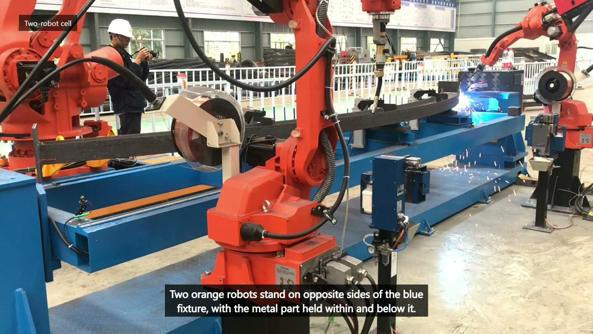
Final main video 00:10 — Two orange robots stand on opposite sides of the blue fixture, with the long metal member held within it.
Build a joint-access map before assigning robot positions
For each required joint, record the permitted torch angles, start and end access, cable envelope, nearby clamps, and a clear retreat. Then classify the joint as open, restricted, re-presentation required, or outside the proposed automated scope. This map reveals whether two fixed robot positions are sufficient or whether the workpiece, fixture, or robot mounting needs to change.
| Joint condition | Early question | Possible response |
|---|---|---|
| Close to a clamp | Can the torch and neck pass without losing the required angle? | Move the clamp or change its direction |
| Far from the datum | How much position variation reaches the joint? | Improve support or measure presentation |
| Behind a curve | Is there a safe approach and retreat? | Re-present the member or change scope |
| Shared between robots | Can one arm clear before the other enters? | Define ownership and wait states |
Support the member without turning the fixture into an obstacle
A long member needs enough support to control its presentation, but every support consumes access. Select datums that are stable before welding, place supports where they control sag or twist, and locate clamps so the planned torch path remains open. Measure joint position after clamping and again after release; otherwise path corrections can mask fixture or incoming-part variation.
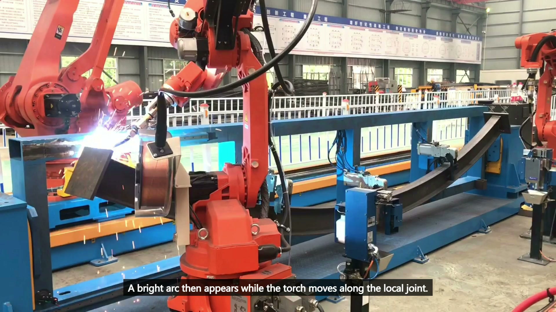
Final main video 00:28 — A welding torch works at a local joint on the long metal member, with arc light and sparks visible.
The fixture must also permit loading, inspection, cleaning, and torch service. Those states often need different clearances from automatic welding. A design that only works with the cell closed and a perfect part already clamped is incomplete.
Sequence by access and verification
The path plan should include weld segments, arc-off moves, robot handoffs, recovery points, and inspection locations. Test the most restricted joint, the longest relocation, and any region where robot envelopes approach one another. Assign each result to a joint number, fixture condition, and program version.
Why not start with the easiest joint?
An easy demonstration can hide the feature that later forces a fixture redesign. The hardest joint exposes the layout limit while changes are still inexpensive.
Does a second robot automatically shorten the cycle?
No. Benefit depends on access allocation, shared-space waiting, fixture behavior, and the required welding and inspection sequence.
What should the physical trial use?
Use production-like members, realistic tack and gap conditions, the proposed supports, and the actual torch and cable package.
Inputs for a long-frame welding study
- Frame drawing and numbered joint list
- Weld regions, preparation, and acceptance criteria
- Incoming tolerances, tack condition, and likely distortion
- Datum, support, clamp, and loading concept
- Torch, cable, robot, and maintenance envelopes
- Output target, changeover range, and recovery rules
Email sales@evsrobot.com or use the EVS International contact page with the member drawing and joint list. EVST can review the access map, support concept, robot allocation, and trial plan.
The footage documents visible frame fixturing and local welding motion. Product identity, robot coordination, welding procedure, cycle performance, and weld acceptance require project validation.