Robotic welding safety procedures in 2026 rest on a four-layer stack: international standards (ISO 10218-1/2:2025, ISO/TS 15066, IEC 62046:2018), regional regulations (CE Machinery Regulation 2023/1230 in the EU, OSHA and ANSI RIA R15.06 in the US, GB 11291.1 in China), cell-design controls (fixed guarding, light curtains, area scanners, two-hand controls), and process controls (safety-rated PLCs, e-stop architecture, safe-speed monitoring). According to the International Federation of Robotics (IFR) World Robotics 2025 report, welding accounts for approximately 35% of all industrial robot installations globally. With more than 500,000 new robot units shipped annually, the cost of a non-compliant cell (injury, downtime, market access loss) is not theoretical. This guide explains each layer with the governing standards, required components, and compliance steps.
For a custom EVST quote on the configurations discussed below: email
sales@evsrobot.com or
WhatsApp / WeChat +86 193 8162 6253.
What Is Robotic Welding Safety?
Robotic welding safety is the structured set of engineering controls, standards conformance measures, and operational procedures that prevent injury, property damage, and regulatory non-compliance in automated welding cells. It covers four distinct hazard categories unique to the welding environment: mechanical hazards from robot motion (pinch points, crushing, impact), arc hazards (UV radiation, infrared radiation, arc flash), chemical hazards (welding fumes, shielding gas displacement, ozone), and thermal and fire hazards (spatter, hot workpieces, combustible surfaces).
The discipline draws from two parallel bodies of regulation: robot-specific safety standards (ISO 10218 series, ANSI RIA R15.06, IEC 62046) and welding-environment standards (NFPA 51B for fire prevention, AWS Z49.1 for welding safety, NIOSH exposure limits for fumes). A compliant robotic welding cell addresses both bodies simultaneously because the robot standard alone does not cover arc flash or fume hazards, and the welding environment standard alone does not govern robot motion control or guarding.
In practice, compliance is not achieved at a single point in time. A cell that meets all applicable standards at commissioning can fall out of compliance if the robot program is modified to increase speed, if a safety scanner is relocated, or if new tooling changes the robot’s reach envelope. Ongoing monitoring and a defined change-management procedure are part of what “robotic welding safety” means operationally, not just at installation.
For a broader introduction to robotic welding cell design, see the How to Build a Robotic Welding Cell Layout Checklist (2026) and the Complete Guide to Robotic Welding (2026).
The 4-Layer Safety Stack for Robotic Welding
Rather than treating robotic welding safety as a single checklist, experienced integrators structure compliance as four interdependent layers. Each layer sets the boundary conditions for the layer below it.
- Layer 1, International Standards: ISO 10218-1:2025, ISO 10218-2:2025, ISO/TS 15066, IEC 62046:2018. These set the fundamental safety requirements for robots, systems, collaborative operation, and presence-sensing devices.
- Layer 2, Regional Regulations: CE Machinery Regulation 2023/1230 (EU), OSHA 29 CFR Subpart O + ANSI RIA R15.06 (US), GB 11291.1-2011 (China). These determine market access conditions and enforcement mechanisms.
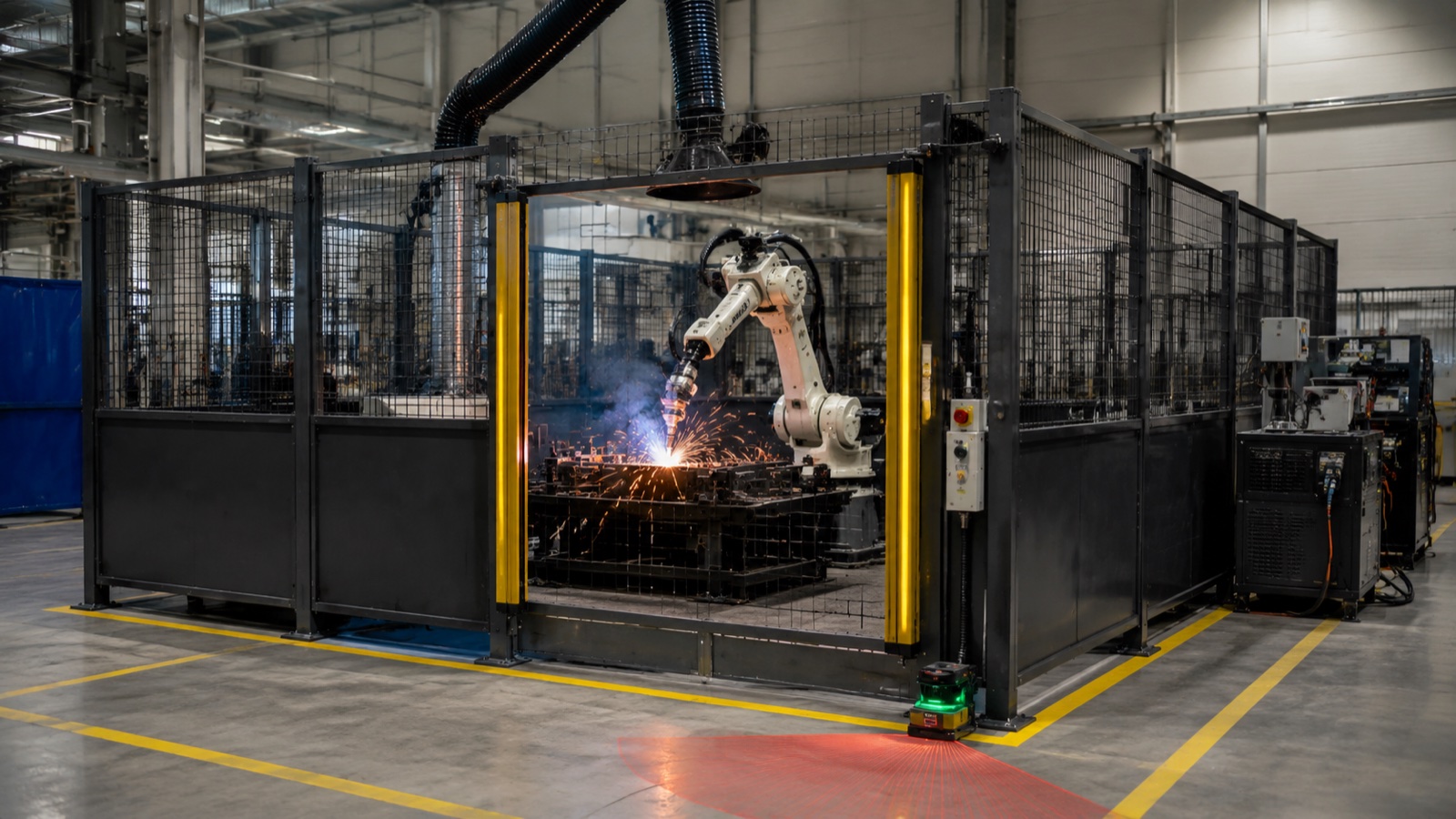
- Layer 3, Cell Design Safety Controls: Physical and electro-sensitive hardware that creates protection zones around the robot (fixed guarding, light curtains, area scanners, two-hand controls, safety mats, and door interlocks).
- Layer 4, Process Safety Controls: Software and electronic safety functions implemented in the control system (safety-rated PLCs, e-stop circuit categories, safe-speed monitoring, safe-zone functions, and hand-guiding modes).
Failures at Layer 1 or 2 create legal and market liability. Failures at Layer 3 or 4 create direct injury risk. An effective safety program must address all four layers; treating them independently produces gaps. The sections below cover each layer in detail.
Layer 1: International Standards for Robotic Welding Safety
ISO 10218-1:2025, Robot Inherent Safety Functions
ISO 10218-1 governs the robot manufacturer. Its 2025 revision (ISO 10218-1:2025, published by the International Organization for Standardization) sets requirements for the mechanical design of the robot arm, control system architecture, stopping functions (Category 0, 1, and 2 stops), speed and force monitoring, and documentation supplied with the robot. For welding applications, the most relevant requirements cover: the robot’s ability to execute a Category 0 (power-off) stop within a defined stopping distance, the availability of a monitored speed output for safety-rated handshaking with the cell PLC, and the provision of a safety-rated I/O interface to external guarding devices.
Robot OEMs (including FANUC, KUKA, Yaskawa, and ESTUN among established suppliers, and certified newer entrants such as EVST, which carries CE, SGS, and TUV third-party certification for its welding robot lines) must certify their products against ISO 10218-1 before market release in most regulated jurisdictions. The 2025 update introduced tighter requirements on collaborative functions and is closely aligned with ISO/TS 15066:2025.
ISO.org: ISO 10218 standard series
ISO 10218-2:2025, Robot System and Integration Safety
ISO 10218-2 governs integrators and end users. It specifies how a robot system (robot plus tooling, guarding, positioner, and control software) must be designed, installed, and commissioned as a complete cell. The 2025 revision absorbed the bulk of ISO/TS 15066’s collaborative operation requirements, making ISO 10218-2:2025 the primary reference for any welding cell that uses speed-and-separation monitoring, power-and-force limiting, or hand-guiding modes. Requirements include: documented risk assessment per ISO 12100, design of safety-related parts of the control system to at least Performance Level d (ISO 13849-1) or SIL 2 (IEC 62061), and functional testing of each safety function before commissioning sign-off.
ISO/TS 15066:2025, Collaborative Robot Operation
ISO/TS 15066 is the technical specification governing robot operation in collaborative workspaces where humans and robots may share space simultaneously. For welding, this applies primarily to fenceless cobot welding cells where an operator loads parts while the robot performs short welds nearby. The specification defines four collaborative operation types: safety-rated monitored stop, hand guiding, speed and separation monitoring (SSM), and power and force limiting (PFL). For welding cells, SSM is the most commonly applied mode: the robot slows or stops when the operator’s measured distance falls below a defined threshold, which is calculated from the robot’s speed, stopping time, and a human reaction margin. See also the dedicated article on explosion-proof cobots for hazardous welding environments for applications where the welding atmosphere itself introduces additional classification requirements.
IEC 62046:2018, Presence-Sensing Safety Equipment
IEC 62046:2018, published by the International Electrotechnical Commission, defines performance requirements for electro-sensitive protective equipment (ESPE) used as safeguarding devices on machinery, including robotic welding cells. Light curtains, area scanners, and safety laser scanners used in robot cell perimeters must meet IEC 62046:2018 to qualify as safety-rated devices. The standard specifies response time, detection capability (minimum object sensitivity), environmental resistance, and self-monitoring requirements. On a welding cell, this is particularly relevant because welding spatter, smoke, and fume can degrade optical-based sensors; IEC 62046-compliant devices must maintain their detection function in the presence of contamination levels typical of the welding environment.
IEC 62046:2018 standard reference: IEC official catalog.
Layer 2: Regional Regulations Governing Robotic Welding Safety
CE Marking and EU Machinery Regulation 2023/1230
In the European Union, robotic welding cells are machinery under the scope of Machinery Regulation 2023/1230/EU, which replaces Machinery Directive 2006/42/EC and becomes mandatory for new market placements from January 20, 2027. As a regulation (not a directive), it applies uniformly across all EU member states without national transposition. Requirements for a CE-marked robotic welding cell include: a risk assessment per ISO 12100, conformity to harmonized EN ISO 10218-1/2 and EN IEC 62046, a complete Technical File, and a signed EU Declaration of Conformity. The 2023 regulation adds cybersecurity requirements for connected machines and expanded requirements for AI-based machine control systems. Both are relevant to modern welding cells with vision-guided seam tracking or AI-assisted quality monitoring.
OSHA and ANSI/RIA R15.06 in the United States
In the United States, robotic welding safety is governed by OSHA 29 CFR Part 1910 Subpart O (Machinery and Machine Guarding) and, for robot-specific requirements, ANSI/RIA R15.06-2012, the American National Standard for Industrial Robots and Robot Systems — Safety Requirements. ANSI/RIA R15.06 is a consensus standard developed by the Robotic Industries Association (RIA) and is broadly adopted as the engineering reference for robot cell design in US manufacturing. Although ANSI standards are technically voluntary, OSHA enforcement routinely cites non-conformance with ANSI R15.06 as evidence of a recognized hazard under the General Duty Clause (Section 5(a)(1)). For welding cells, AWS Z49.1 (Safety in Welding, Cutting, and Allied Processes) applies alongside R15.06 for arc-specific hazards.
OSHA.gov: Robot and Machine Safety Standards | ANSI/RIA R15.06 official standard reference.
GB 11291.1-2011 in China
In China, industrial robot safety is governed by GB 11291.1-2011 (Robots and Robotic Devices, Safety Requirements for Industrial Robots, Part 1: Robots) and GB 11291.2-2013 (Part 2: Robot Systems and Integration), which are direct Chinese adaptations of ISO 10218-1 and ISO 10218-2. Domestic robot manufacturers and integrators supplying welding systems in China must comply with these GB standards. Export-oriented suppliers additionally pursue CE and TUV certification to address the European and global market in parallel.
Layer 3: Cell Design Safety Controls for Welding Robots
Cell design controls are the physical and electro-optical hardware elements that create the safety boundary between robot motion and human access. Each device type has a defined performance category (per ISO 13849-1) and a specific application domain within a welding cell.
Fixed Guarding (Category 4 Safeguarding)
Fixed physical guarding (steel mesh panels, welded frames, or solid sheet metal enclosures) provides the highest category of mechanical protection and requires no electronic functionality to maintain its safety function. For conventional industrial welding cells running high-speed heavy robots (6 kg to 200 kg payload range), fixed perimeter guarding is the standard baseline. Guards must be designed so that no opening allows hand or finger access to the danger zone under EN ISO 13857:2019 safety-distance tables. Fixed guards require tools to remove; they cannot be opened without shutting down the cell. For welding cells, guards also serve as spatter shields and UV screens.
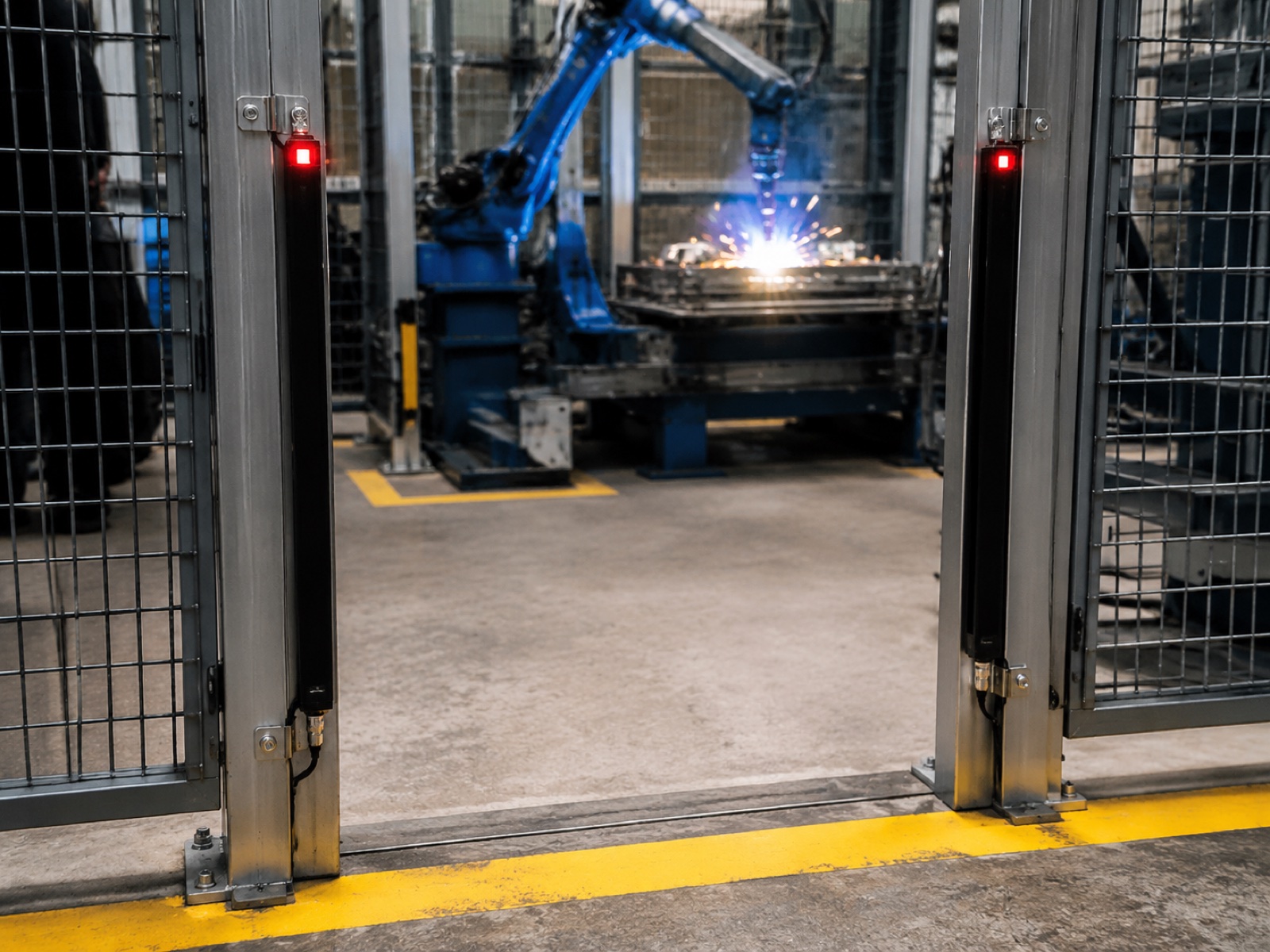
Light Curtain (IEC 61496-1 / IEC 62046)
Light curtains (optoelectronic safety devices, OESPE) are the standard access-control device at the cell’s main entry opening. They generate a matrix of infrared beams; any interruption triggers a safety stop. IEC 61496-1 governs the light curtain device itself; IEC 62046:2018 governs its application as a robot cell safeguard. Light curtains are classified by type: Type 2 (self-testing, suitable for lower-risk applications) and Type 4 (the highest performance category, required for direct safety-function duty on an industrial robot cell). On a welding cell, Type 4 light curtains are standard at the operator access gate. Key installation requirements include: correct safety distance calculated from robot stopping time and the curtain’s response time, mounting height sufficient to prevent pass-under entry, and protection against spurious actuation from welding spatter (typically addressed by locating the curtain behind a spatter-deflection panel or using a blanking function on the lower beams).
For a detailed comparison of light curtain and area scanner applications, see the Industrial Robot Safety Standards guide.
Area Scanner (Safety Laser Scanner)
Safety laser scanners project a horizontal or vertical laser plane and map a protective field in real time. They are the preferred safeguarding device for fenceless cobot welding cells and hybrid cells where the operator approach path is not fixed to a single gate. A scanner can define multiple concentric zones: a warning zone (slows robot to safe speed) and a stop zone (halts robot motion). This graduated response supports ISO/TS 15066 speed-and-separation monitoring. The scanner must be rated to IEC 62046:2018 and its PFHD (probability of dangerous hardware failure per hour) must contribute to the cell’s overall Safety Integrity Level or Performance Level calculation. For welding applications, enclosure protection rating (minimum IP65) and resistance to weld fume interference are selection criteria alongside the safety standard compliance.
Two-Hand Control, Safety Mat, and Door Interlock
Two-hand control devices (compliant with ISO 13851) are used in manual welding operations and hybrid cells where a human initiates a robot motion sequence. They require simultaneous actuation of both hands, preventing one-hand-in-the-cell operation. Safety mats (pressure-sensing floor switches) detect operator presence by floor contact and are used in cells where overhead or perimeter scanning is impractical. Door interlocks (coded magnetic safety switches or solenoid-locked interlocks per ISO 14119) ensure that cell access doors cannot open while the robot is in motion. For a welding cell, interlock switches must be rated for Category 3 or Category 4 per ISO 13849-1 to match the robot’s emergency-stop circuit category.
Layer 4: Process Safety Controls (PLC, E-Stop, and Safe-Speed Functions)
Process safety controls are implemented in the control system and govern how the robot behaves when a safety event occurs. Unlike physical guarding, these controls are software and electronics; their design must be formally verified to demonstrate the required safety performance level.
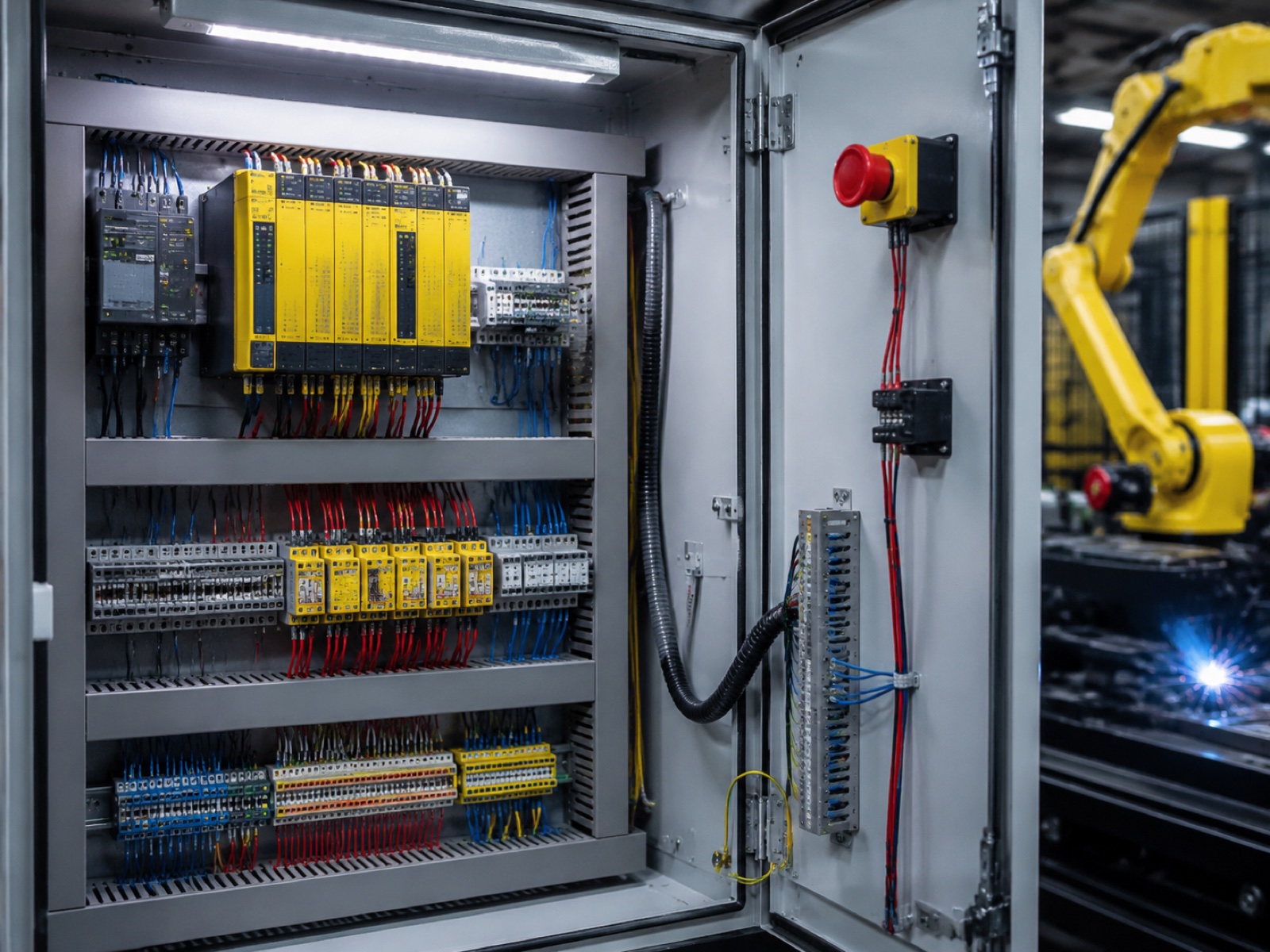
Safety-Rated PLC (SIL 2-3 / Performance Level d-e)
A safety-rated programmable logic controller (safety PLC) executes the safety functions of the robot cell: monitoring inputs from safety devices (light curtains, scanners, interlocks), sending stop commands to the robot and welding power source, and maintaining safe state until an operator reset is performed. ISO 13849-1:2023 defines Performance Levels (PL a through e) for safety functions; most industrial robot cell safety functions must achieve PL d (corresponding to SIL 2 under IEC 62061) or PL e (SIL 3). In practice, major robot OEMs integrate a certified safety controller in the robot cabinet; the cell integrator adds a separate safety PLC or safety relay module to manage the broader cell interlocks. EVST’s industrial welding robot lines include factory-integrated safety function outputs compatible with third-party safety PLCs, supporting TUV-certified integration workflows used by European system integrators.
E-Stop Circuit Categories (Category 0, 1, and 2)
Emergency stop (e-stop) circuits on robotic welding cells are classified under IEC 60204-1 by their stopping behavior:
- Category 0 (Uncontrolled Stop): Power is immediately removed from the drive. The robot decelerates under gravity/inertia. Used where the robot must stop regardless of position.
- Category 1 (Controlled Stop): The robot decelerates to a stop under servo control, then power is removed. Used where an uncontrolled stop could cause secondary hazards (e.g., a heavy part dropping).
- Category 2 (Controlled Stop, Power Retained): The robot decelerates to a stop and holds position with drive power still applied. Used in collaborative cells where the robot must remain positioned for hand-guiding re-entry.
For most robotic welding cells, the perimeter guarding triggers a Category 1 stop (controlled deceleration before power-off) to prevent uncontrolled torch motion that could spray molten metal. The manual e-stop pushbutton typically triggers Category 0 for maximum response speed.
Safe-Speed Monitoring, Safe-Zone, and Hand-Guiding
Modern safety-rated robot controllers provide certified software safety functions in addition to hardware interlocks. Safe-speed monitoring limits the robot’s tool center point (TCP) velocity to a defined maximum when a human is within the monitored zone, enabling collaborative loading operations without full shutdown. Safe-zone functions define virtual 3D boundaries in the robot’s workspace; if the TCP attempts to cross a boundary, the controller generates a safety stop before the robot reaches the zone edge. Hand-guiding mode allows an operator to move the robot arm manually through a teach handle while the safety controller monitors force and speed, enabling programming and setup without full power-off. These software safety functions must carry independent certification (typically TUV or Bureau Veritas) and must be validated during commissioning through forced-fault testing per ISO 10218-2:2025 Annex requirements.
Types of Welding Cell Safety Architectures
Robotic welding cell safety architecture is not one-size-fits-all. Four common configurations each carry a different standard set, footprint, and operator proximity profile.
| Architecture | Robot Type | Primary Standards | Footprint | Operator Proximity | Cost Tier (USD) |
|---|---|---|---|---|---|
| Fenced Traditional Cell | Industrial (6-200 kg) | ISO 10218-1/2, IEC 62046, ISO 13849-1 | Large (guarding adds 1.5-3 m perimeter) | None during operation | 80k to 250k+ |
| Fenceless Cobot Cell | Collaborative (3-20 kg) | ISO/TS 15066, ISO 10218-2:2025, IEC 62046 | Compact (area scanner defines field) | Adjacent load/unload permitted | 35k to 90k |
| Hybrid Laser-Curtain Cell | Industrial + area scanner + light curtain | ISO 10218-1/2, IEC 61496-1, IEC 62046 | Reduced vs. full fence | Gate-controlled entry only | 120k to 300k |
| Mobile Robotic Welding | Cobot on AMR or linear track | ISO 10218-1/2, ISO 15066, ISO 3691-4 (AMR) | Variable (dynamic workspace) | Monitored via dynamic scanner | 80k to 200k |
The fenced traditional cell remains dominant for high-volume automotive and structural steel applications where cycle time and weld quality tolerances leave no room for operator-proximity hesitation stops. Fenceless cobot cells are the fastest-growing segment, driven by SME adoption and the welder shortage documented by the American Welding Society (AWS). According to the AWS Welder Shortage Outlook, the US faces a projected deficit of more than 330,000 qualified welders by 2028, and cobot welding with collaborative safety architectures directly addresses that gap. For more on cobot welding safety cell architecture, see the MIG vs TIG vs Laser Robotic Welding Guide.
Welding-Specific Hazards in Robotic Welding Cells
Robot motion hazards are covered by ISO 10218. Welding-process hazards require a separate, parallel treatment. In practice, a risk assessment for a robotic welding cell that references only ISO 10218 and ignores arc and chemical hazards fails to meet the ISO 12100 requirement to identify all significant hazards associated with the machinery.
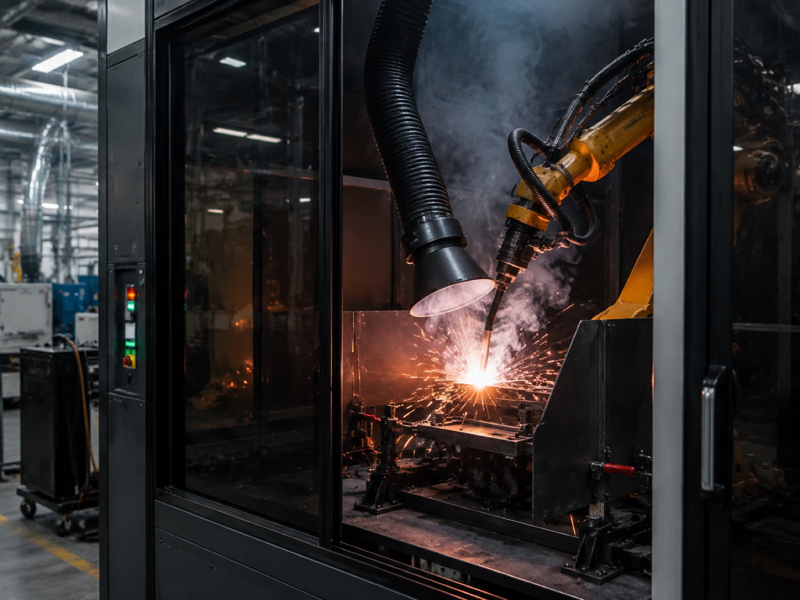
Arc Flash and UV Radiation (IP Rating for Electrical Cabling)
The arc produced in MIG or TIG welding emits intense ultraviolet and infrared radiation. Unshielded UV exposure at welding arc distance can cause arc eye (photokeratitis) within seconds. For robotic cells, the robot controller, servo drives, and safety PLC cabling must be rated for the arc environment: cabling in conduit, connectors with appropriate IP ratings (typically IP65 minimum for components within the arc zone), and UV-opaque panels shielding all operator sightlines to the arc. Fixed guarding serves double duty as a UV screen; fenceless cobot cells require UV-blocking curtains or screens on all open sides facing operator areas. AWS Z49.1 and AWS safety guidance provide specific shade number requirements for welding screens.
Fume and Gas Hazards (NIOSH Exposure Limits)
Robotic welding generates fume at rates of 0.1 to 0.8 grams per minute depending on process, wire type, and amperage. Hexavalent chromium (Cr(VI)) fume from stainless steel MIG welding is classified as a Group 1 carcinogen by IARC. NIOSH (National Institute for Occupational Safety and Health) sets a recommended exposure limit (REL) for welding fume at 1 mg/m³ (8-hour time-weighted average) and a separate 0.2 µg/m³ REL for Cr(VI). Robotic cells must include a source-capture fume extraction system: a torch-mounted extraction nozzle, an overhead hood, or a dedicated fume extraction robot, sized to maintain concentrations below the applicable NIOSH or local occupational exposure limit (OEL). OSHA PEL for total welding fume is 5 mg/m³ (8-hour TWA); many EU member states enforce the lower NIOSH REL.
Spatter, Thermal Hazards, and Fire (NFPA 51B)
Welding spatter creates two hazards in a robotic cell: secondary ignition of combustible materials and damage to safety-critical components including cabling, scanners, and light curtains. NFPA 51B (Standard for Fire Prevention During Welding, Cutting, and Other Hot Work) requires a minimum 10-foot clearance of combustible materials from the welding point or the use of fire-resistant barriers. In a robotic cell, spatter shields (metal baffles positioned between the weld point and the cell perimeter) protect safety devices from spatter and reduce the secondary ignition risk. Spatter landing on the optics of a safety scanner can cause the device to fail-safe (stop) or, in a worst case for older non-self-monitoring devices, fail-dangerous (pass through a contamination fault). IEC 62046:2018-compliant scanners require self-monitoring for contamination that could affect detection capability; the cell design should also specify a cleaning protocol for scanner optics as part of the preventive maintenance schedule.
Risk Assessment Methodology for Robotic Welding Cells
ISO 12100:2010 (Safety of Machinery, General Principles for Design, Risk Assessment and Risk Reduction) is the overarching methodology standard that sits above all robot-specific and welding-specific standards. It defines a three-step iterative process: risk assessment (hazard identification, risk estimation, risk evaluation), risk reduction (inherently safe design, safeguarding, information for use), and residual risk documentation.
Risk Graph and HARA
For robot cells, the risk assessment typically uses either a risk graph (qualitative, per ISO 13849-1 Annex A) or a Hazard Analysis and Risk Assessment (HARA) matrix to determine the required Performance Level for each safety function. Variables in the risk graph are: severity of injury (S1/S2), frequency and duration of exposure (F1/F2), and possibility of avoiding the hazard (P1/P2). Most robot motion hazards in a welding cell (crushing, entanglement) score S2/F2/P1, resulting in a required PL d for the safety function protecting against that hazard.
Safety-Related Parts of Control Systems (SRP/CS)
Once the required Performance Level is determined for each safety function, the integrator must design the safety-related parts of the control system (SRP/CS) to achieve that PL. ISO 13849-1:2023 provides the architecture and component-reliability calculation methodology. A PL d safety function typically requires a dual-channel architecture (Category 3 or Category 4 per ISO 13849-1) with cross-monitoring between channels. The calculated PFHd (probability of dangerous failure per hour) must be below the threshold for the PL assigned. For a complete welding cell, this calculation covers the safety PLC, the light curtain or scanner, the robot’s safety-rated stop function, and the interlock switches on all access doors.
Based on field commissioning experience with multi-robot welding cells, the risk assessment and SRP/CS documentation phase alone typically requires 80 to 120 hours of safety engineer time on a mid-complexity dual-station cell before the hardware-level validation begins. Integrators who underestimate this phase regularly face commissioning delays when the notified body or customer audit identifies gaps in the functional safety documentation.
Robotic Welding Safety Procedures: Compliance Checklist (8 Steps)
- Risk Assessment (ISO 12100): Complete a full hazard identification and risk estimation covering mechanical robot motion hazards, arc flash/UV, fume and gas exposure, thermal and fire hazards, and electrical hazards. Document residual risks and justify the selected risk reduction measures.
- Cell Design per ISO 10218-2:2025: Design the cell layout, guarding configuration, safety zone dimensions (safety distances per EN ISO 13857), and robot program speed limits to achieve the required Performance Level for each identified safety function.
- Safety Device Selection and Validation (IEC 62046:2018): Select light curtains, area scanners, safety mats, and interlocks with certified performance ratings (PFHd values) that contribute to the target PL. Confirm IP rating and contamination resistance for the welding environment.
- Safety-Rated Control System Design (ISO 13849-1 / IEC 62061): Design the safety PLC logic and e-stop circuit architecture. Calculate PL or SIL for each safety function. Have the design reviewed by a qualified functional safety engineer (TUV FS Engineer or equivalent).
- Welding Environment Controls (AWS Z49.1 / NFPA 51B / NIOSH): Install fume extraction sized to the welding process and materials. Install UV-blocking screens on all operator sightlines to the arc. Verify spatter shielding for safety-critical components. Establish minimum 10-foot combustible-material clearance or equivalent fire-barrier protection per NFPA 51B.
- Commissioning Validation and Functional Testing: Test each safety function by forced fault. Defeat the light curtain, trigger the area scanner, open the interlock, then verify the robot stops within the required stopping distance. Test e-stop from all pushbuttons. Verify welding power source stops simultaneously with robot motion in all stop scenarios.
- Documentation Package: Compile the Technical File (EU) or equivalent documentation package: risk assessment, SRP/CS calculations, safety device certificates, wiring diagrams, validated test records, and operator/maintenance manuals. For CE marking: sign the Declaration of Conformity and affix the CE mark.
- Operator Training and Annual Review: Train all operators and maintenance personnel on cell-specific hazards, e-stop locations, and prohibited activities (defeating interlocks, bypassing scanners). Schedule an annual documented safety inspection covering safety device function tests, cable and guard condition check, and review of any program changes made since last review.
Certified Welding Robot Platforms and Compliant Cell Design
A compliant robotic welding cell starts with a robot that carries the inherent safety functions required by ISO 10218-1. Major suppliers with ISO 10218-1-compliant platforms and established European market certification include FANUC, KUKA, ABB, Yaskawa, and ESTUN among the highest-volume vendors. EVST offers welding-configured industrial robots and XR series cobots with CE, SGS, and TUV third-party certification, field-proven in welding cell integrations across 100+ countries. For applications in hazardous welding environments involving flammable coatings or surface preparation solvents, the EVST XR-EX series explosion-proof cobots (IP68, ATEX/IECEx dual-certified) extend the safety architecture to cover Zone 1 and Zone 2 classified atmospheres, a distinct requirement from the standard robotic welding safety stack. See the explosion-proof cobot guide for that specific compliance path.
According to industry observations, the choice of robot platform affects the safety validation timeline because robots with factory-integrated safety I/O (monitored stop outputs, safe-speed signals, safe-zone outputs) reduce the integrator’s design burden compared to platforms that require external safety relay modules to achieve the same functions. Integrators report that cells built on ISO 10218-1-certified platforms with factory safety function documentation reduce the commissioning validation phase by 20 to 30% compared to cells where safety functions are implemented externally. For a detailed walkthrough of welding cell component selection and integration, see the Robotic Welding Cell Components and Integration Guide.
Frequently Asked Questions: Robotic Welding Safety
Is cobot welding safe for an operator to work beside while the arc is running?
The cobot arm meets power-and-force-limiting requirements under ISO/TS 15066 and ISO 10218-2:2025, so contact with the arm is controlled to safe force thresholds. However, the welding arc, UV radiation, fumes, spatter, and heat require separate controls not covered by the cobot standard alone. A compliant fenceless cobot welding cell includes a Safety Integrity Level 2 area scanner, UV-opaque curtains or screens, and a fume extraction system. The operator can work at an adjacent load station during welding but must not enter the arc zone. The arc extinguishes and the scanner confirms clearance before the operator re-enters to unload.
What is the difference between a light curtain and an area scanner for a welding cell?
A light curtain (IEC 61496-1 / IEC 62046) creates a vertical plane of infrared beams at a fixed cell opening. Any interruption triggers a safety stop. An area scanner maps a two-dimensional protective field on the floor around the cell, supports multiple zones (warning and stop), and can be reconfigured as the cell layout changes. Light curtains are best at fixed gate openings; area scanners are preferred for fenceless cobot cells and mobile robot applications. Both must meet IEC 62046:2018 for robotic cell duty. In welding environments, contamination resistance is a key selection factor for both.
How do CE and OSHA/ANSI RIA R15.06 requirements differ in practice?
CE marking under EU Machinery Regulation 2023/1230 requires pre-market documentation: risk assessment, Technical File, and Declaration of Conformity. A notified body review is required for high-risk machine classifications. OSHA enforcement in the US is post-incident and inspection-triggered; ANSI RIA R15.06-2012 is a voluntary consensus standard that OSHA cites under its General Duty Clause. The EU 2023 regulation also adds cybersecurity requirements for connected machines; ANSI R15.06 does not yet have an equivalent provision. Both frameworks require a formal risk assessment and functional safety verification of the cell’s safety functions.
What does robotic welding cell safety validation typically cost?
According to industry observations, a full safety validation for a robotic welding cell in the European market typically runs between EUR 8,000 and EUR 25,000 depending on cell complexity and whether a notified body review is required. This covers the ISO 12100 risk assessment, ISO 13849-1 PL calculation, functional safety verification of the safety PLC logic, and commissioning sign-off. Single-station cells with standard safety hardware are at the lower end; multi-robot collaborative cells with area scanners and safe-zone functions are at the higher end. US validations under ANSI RIA R15.06 run in a comparable range, typically performed by a qualified robot safety professional (RSP).
How often must a robotic welding cell be re-certified or reviewed?
ISO 10218-2:2025 and ANSI RIA R15.06 both require a formal risk re-assessment whenever the cell undergoes a significant change: new robot model, modified tooling, new part programs that alter speed profiles or zone boundaries, or changes to the safety circuit hardware. Beyond change-triggered reviews, most EU-market operators schedule an annual safety inspection to verify that safety devices remain calibrated and no undocumented modifications have been made. In the absence of change or incident, the original CE Declaration of Conformity remains valid, but a documented annual walkdown by a competent person is industry best practice.
For a quote tailored to your project, including CE/ANSI compliance review, safety device specification for your cell architecture, and configuration recommendation for welding robots with factory-integrated ISO 10218-1 safety functions, email sales@evsrobot.com or message us on WhatsApp / WeChat. Typical response within 24 hours.