Robotic Welding Software Stack: Offline Programming, Simulation & Digital Twin (2026)
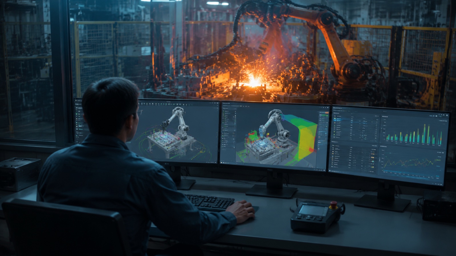
The 2026 robotic welding software stack has four layers: (1) offline programming (OLP) for path planning, covering tools from RobotStudio and RoboGuide to Octopuz and DELMIA; (2) simulation and cycle-time validation before a program reaches the factory floor; (3) digital twin platforms (Siemens Tecnomatix, Rockwell Emulate3D, NVIDIA Omniverse) that maintain real-time parity with the physical cell; and (4) AI teach-free systems that auto-generate weld paths from CAD or 3D scan data, compressing setup from days to minutes.
1. Offline Programming (OLP): Vendor-Native and Vendor-Neutral Tools
Robotic welding offline programming moves path definition from the factory floor to an engineering workstation. The engineer imports the workpiece CAD model, positions the virtual robot, defines torch orientation, travel speed, and weave parameters, runs collision and reachability checks, then exports post-processed controller code for upload. The physical robot cell keeps running production while programming work is underway, which is the primary economic argument for OLP over manual teach.
According to IFR World Robotics data, OLP adoption among arc-welding robot users in automotive tier-1 suppliers has risen from roughly 40 percent in 2020 to an estimated 65 percent or more in 2025, driven by shorter product lifecycles and the growing variety of weld joint geometries on EV battery enclosures and structural frames.
Vendor-Native OLP Platforms
Each major robot OEM ships its own simulation and OLP environment, tightly integrated with the brand’s proprietary controller and motion kernel:
- ABB RobotStudio, the most widely used vendor-native OLP platform globally, with built-in RAPID code generation, coordinated motion support, and a welding power-source library covering Fronius, Lincoln, and Miller interfaces. RobotStudio’s virtual controller runs the same firmware as the physical IRC5/OmniCore controller, which closes the sim-to-real gap for cycle-time prediction.
- FANUC RoboGuide, FANUC’s simulation suite supports the full TP (teach pendant) language and includes WeldPRO, a welding-specific module for torch orientation optimisation and multi-layer path planning. RoboGuide is frequently cited in automotive body-shop OEM validation workflows.
- Yaskawa MotoSim EG-VRC, MotoSim’s virtual robot controller replicates the Yaskawa DX200/YRC1000 motion kernel, allowing cycle-time predictions that match field results within ±5%.
- KUKA Sim, integrated with the KUKA.WorkVisual I/O configuration tool, enabling complete cell layout simulation from robot motion through to safety PLC logic.
- Universal Robots URSim, a software simulator for the UR cobot family, relevant for light-gauge welding applications and collaborative welding setups where a UR arm drives a MIG torch at lower duty cycles.
The main constraint of vendor-native OLP is lock-in: each platform generates code for its own brand only. Mixed-fleet cells (ABB robot, FANUC positioner axis) require additional post-processors or a vendor-neutral layer above.
Vendor-Neutral OLP Platforms
Vendor-neutral tools generate post-processed code for multiple robot brands from a single CAD-based environment. For welding, the most commonly specified platforms are:
- Octopuz, built specifically for arc and spot welding, with a weld parameter library and path-optimisation logic that accounts for torch access angle constraints. Supports 40+ robot brands and is widely adopted in heavy fabrication and pressure-vessel shops.
- Visual Components, strong in layout simulation and multi-robot cell planning; welding-specific functionality through add-on modules. Often selected when the priority is overall line throughput rather than detailed torch parameter management.
- FastSuite Edition 2 (Cenit), positioned for complex multi-robot cells and process-intensive applications; integrates with Siemens Tecnomatix Process Simulate for digital twin connectivity.
- RoboDK, a lower-cost, accessible OLP option that covers 500+ robot models. Less comprehensive on welding-specific features (multi-pass sequencing, WPS parameter export) but widely used in job shops and educational settings for its low entry cost.
- DELMIA Robotics (Dassault Systèmes), part of the 3DEXPERIENCE platform, allowing robot programming within the same environment as product design and manufacturing planning. The strongest choice where PLM integration and MBOM traceability are requirements, as in automotive OEM body shops.
- Process Simulate (Siemens Tecnomatix), the incumbent in automotive-OEM body-in-white (BIW) programs, where the same tool drives both offline programming and production simulation. Supports coordinated multi-robot sequences and has a native digital twin bridge to the Tecnomatix plant simulation layer.
Vendor-Native vs Vendor-Neutral: Comparison
| Dimension | Vendor-Native (RobotStudio, RoboGuide, MotoSim, KUKA Sim) | Vendor-Neutral (Octopuz, DELMIA, Visual Components, RoboDK) |
|---|---|---|
| Robot brand coverage | Single brand (own OEM) | Multi-brand (40–500+ models depending on tool) |
| Controller fidelity | Exact virtual controller — highest sim-to-real accuracy | Post-processor model — accuracy depends on post-processor quality |
| Welding-specific features | Deep (native WPS, process libraries, power-source interface) | Variable; Octopuz and Process Simulate are strongest; RoboDK is limited |
| PLM/MES integration | Limited to OEM ecosystem | Strong in DELMIA / Process Simulate; REST/OPC-UA in others |
| Seat cost (indicative) | USD 5,000–15,000/yr (often bundled with robot purchase) | USD 8,000–30,000/yr depending on module depth |
| Best fit | Single-brand robot fleet, high OLP volume, OEM body shops | Mixed-brand fleets, job shops, facilities requiring PLM traceability |
According to Interact Analysis welding automation market research, the global robotic welding software market (OLP, simulation, and digital twin combined) was valued at approximately USD 1.4 billion in 2024 and is forecast to reach USD 2.6 billion by 2029, with AI-augmented path generation identified as the fastest-growing sub-segment. Vendor-neutral OLP tools are gaining share in non-automotive general fabrication as mixed-brand robot fleets become more common.
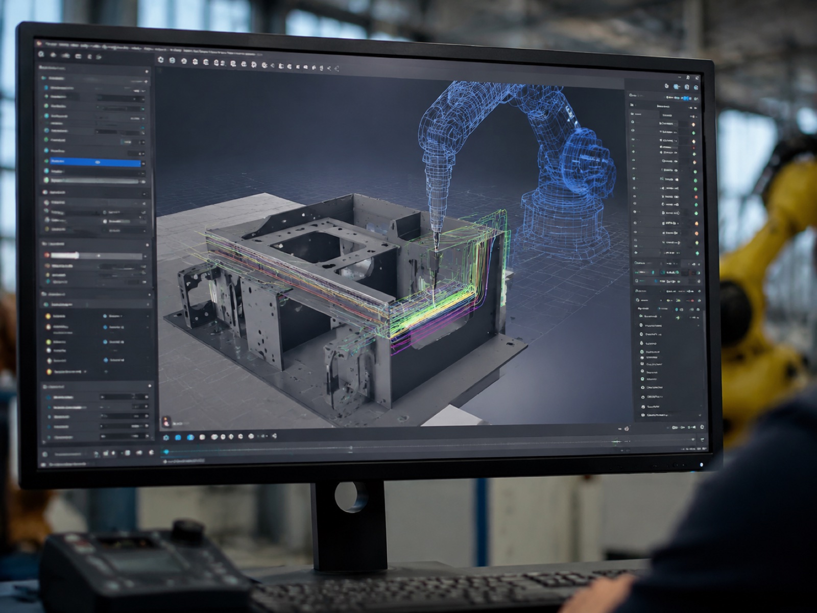
2. Simulation and Cycle-Time Validation
Simulation covers the analytical layer that runs before code reaches the production controller. Modern OLP simulation tools address four specific failure modes that direct teach cannot catch until the robot is already in the cell:
Collision Detection
Collision checking tests the torch, cable dressing, and robot links against the workpiece, fixture, positioner, and cell structure across every point in the programmed path. In practice, this is where most new OLP programs generate corrections: the torch approaches the back of a deep-groove weld and the robot elbow collides with the fixture frame at a waypoint that looked clear in the 2D drawing. Simulation catches this in minutes; discovering it during a production trial can damage a torch worth USD 2,000–5,000 and delays commissioning by days.
Reachability and Singularity Avoidance
A robot cell layout may look geometrically correct but still contain path segments where the robot passes through or near a wrist singularity (a configuration where two joint axes align, causing a mathematically undefined motion). Most OLP tools highlight singularity-risk zones in the path preview and allow the engineer to modify torch angle or robot base position to route around them before any physical trial.
Cycle-Time Prediction
According to industry observations, cycle-time prediction within modern OLP simulation platforms runs within ±5–8% of real-world measured cycle time when the robot kinematic model and controller motion parameters are correctly configured. The residual error comes primarily from acceleration/deceleration ramp settings and air-cut segments near singularities where the robot slows below maximum speed. Calibrating simulation motion parameters against a single production sample run brings prediction error to ±3% or better for standard fillet-weld geometries. This accuracy matters because a 10% cycle-time overestimate on a high-volume part can cost weeks of throughput per year.
Multi-Robot Coordination
Where two or more robots work simultaneously on a single workpiece (common in automotive BIW and structural fabrication cells), simulation becomes mandatory rather than optional. Coordinating two robots on one fixture requires interference-zone management: the planner must define exclusion volumes that prevent simultaneous arm entry and sequence the torch approach so that both robots maintain maximum arc-on time without waiting unnecessarily. Without simulation, this scheduling is impossible to validate without extensive physical trials.
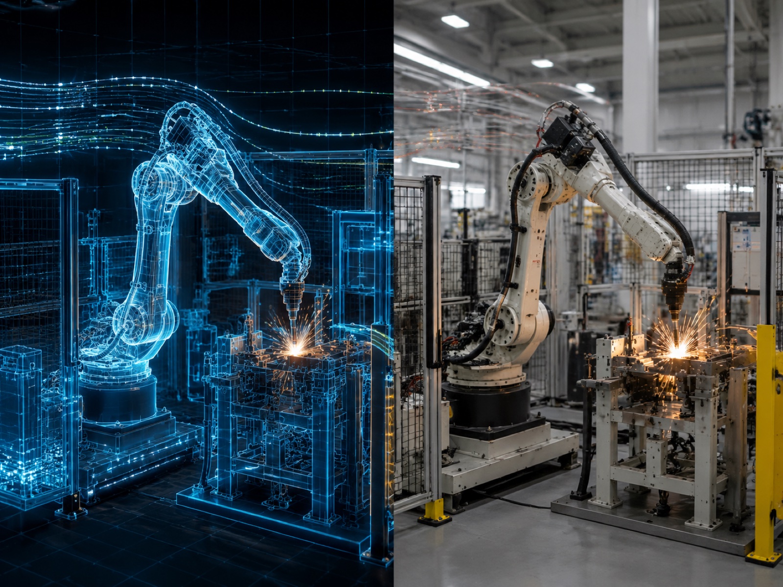
3. Digital Twin: Real-Time Production-Floor Parity
A digital twin extends simulation from a one-time pre-deployment check into an ongoing live model of the operating cell. The key distinction: simulation runs once and then the physical cell takes over; a digital twin maintains a bidirectional data link so the virtual model reflects actual robot position, positioner angle, arc parameters, and sensor readings in real time.
Platform Options
Three platforms are most commonly specified for welding cell digital twins in 2026:
- Siemens Tecnomatix Plant Simulation / Process Simulate, the incumbent in automotive OEM programs. Tecnomatix connects to the Siemens Totally Integrated Automation (TIA) Portal and SINUMERIK/SIMATIC controllers over OPC-UA, supporting real-time throughput monitoring, material-flow analysis, and bottleneck detection across entire production lines, not just individual robot cells.
- Rockwell Automation Emulate3D, a discrete-event simulation and digital twin tool that integrates with Studio 5000 PLC logic, allowing the virtual cell to run actual PLC ladder code in emulation before physical installation. Commonly specified in North American general fabrication where Rockwell Allen-Bradley controls are the plant standard.
- NVIDIA Omniverse Isaac Sim, a physically accurate robot simulation built on Universal Scene Description (USD), with real-time ray-traced rendering and native ROS 2 integration. Isaac Sim is gaining traction as the platform for AI-augmented welding cells where the digital twin must also serve as a synthetic data generator for training 3D vision models and path-planning neural networks.
Use Cases in Welding
What-if scenario testing: A new workpiece variant arrives mid-production run. The digital twin lets the process engineer validate a modified OLP program against the live cell configuration, including current fixture state and positioner calibration offsets, before interrupting production. Testing a path change that would require 4 hours of physical trials can be done in under 30 minutes in the digital twin.
Predictive maintenance: The digital twin tracks cycle-time drift over time. A gradual increase in cycle time on a coordinated-motion positioner sequence, without any change in robot velocity settings, is a reliable early indicator of positioner servo wear or encoder offset drift. Catching this before it causes a missed weld position reduces unplanned downtime.
MES feedback loop: Digital twin data (completed welds per shift, arc-on time, defect-stop events) feeds the MES production record, enabling traceability at the weld-bead level. This is increasingly required in aerospace and pressure-vessel fabrication where ISO 3834 quality system requirements mandate weld process records linked to specific work orders.
According to NVIDIA’s published Omniverse Industrial use-case data, more than 700 industrial companies were using Omniverse for digital twin and synthetic data generation applications as of early 2026, with robotic manipulation and welding cell simulation among the top three application categories. Isaac Sim’s physically accurate rendering enables 3D vision models trained on synthetic weld scenes to transfer to real cells with minimal additional real-world data collection.
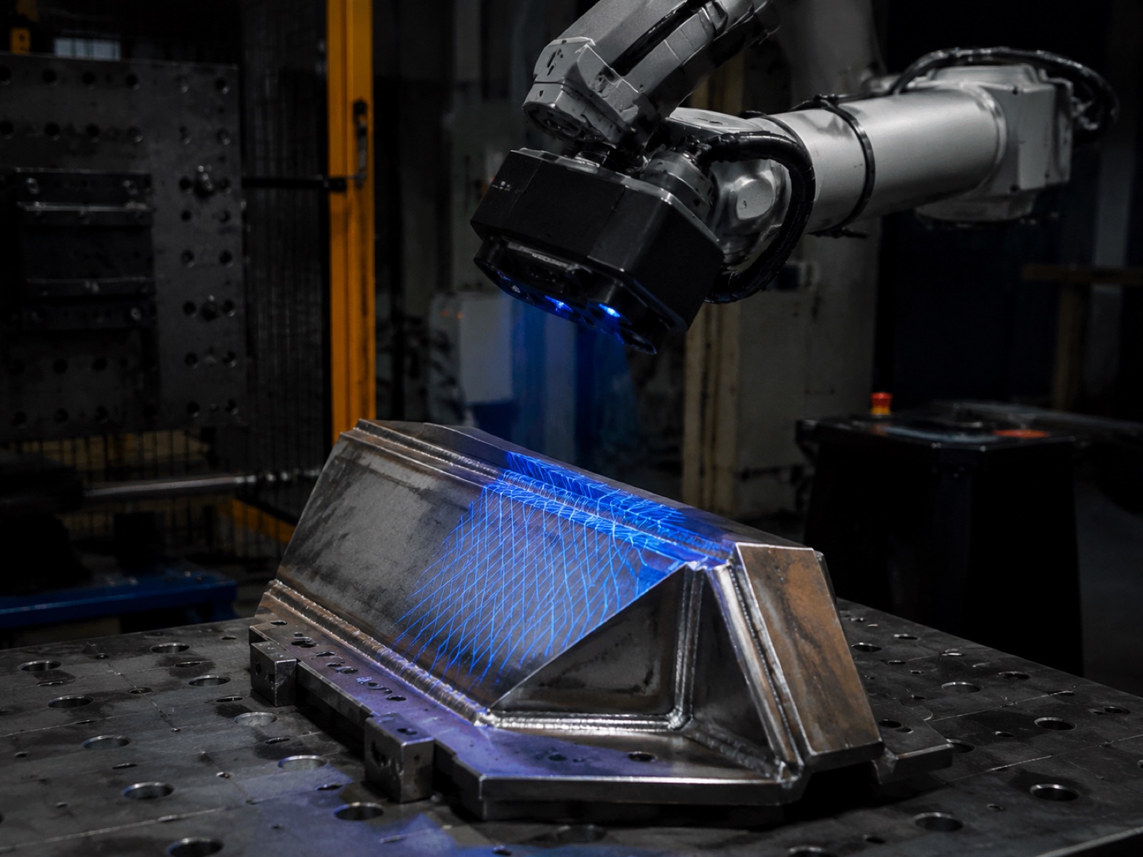
4. AI and Teach-Free Systems: Auto-Path Generation from 3D Scan
The fourth layer of the 2026 welding software stack moves path generation from the engineering workstation entirely: a 3D scanner or structured-light camera captures the workpiece, extracts the weld seam geometry, and generates a robot program automatically, with no manual waypoint definition. Programming time compresses from hours (OLP) to minutes.
How 3D Scan-to-Path Works
The core pipeline has three stages. First, a structured-light or time-of-flight scanner generates a dense point cloud of the workpiece. Second, seam-detection algorithms (trained on annotated weld geometry datasets) identify joint type, orientation, and fit-up gaps. Third, the path planner generates torch waypoints, approach angles, travel speeds, and weave parameters as a robot program, applying process rules from a pre-loaded welding procedure library.
Systems operating in this space include Inrotech AdaptiveARC (a Danish specialist with strong deployment in shipbuilding heavy-plate welding), ABB’s SmartShot feature set (integrated within RobotStudio’s welding module for adaptive arc on known joint geometries), and the EVS-AI welding system from EVST, which combines a 3D vision auto-scan module with a self-learning intelligent engine, EtherCAT 1 kHz motion control, and the RX welding process library covering pre-loaded typical weld geometries and multi-pass sequences. EVST’s EVS-AI system carries CE, SGS, and TUV third-party certification, relevant for buyers integrating into certified quality systems.
Foundation Model Approaches
At the research and early-pilot end of the spectrum, VLA (vision-language-action) foundation models such as Physical Intelligence’s pi-zero and NVIDIA GR00T are being evaluated for welding path generation. These models learn manipulation behaviors from large cross-task demonstration datasets and can, in principle, generalize to new weld joint geometries without retraining. As of 2026, VLA approaches in welding remain in early industrial pilot stages: the stochastic inference behavior and limited explainability of neural-network-generated paths create barriers to deployment in applications requiring ISO 3834 or AWS D1.1 weld procedure qualification traceability. Deterministic scan-to-path systems, where the path generation algorithm can be audited and the welding parameters are drawn from a qualified WPS library, are the production-ready choice for the near term.
When Teach-Free Works vs When OLP Still Wins
| Condition | Teach-Free / 3D Scan-to-Path | Manual OLP |
|---|---|---|
| Part geometry | Regular joints (fillet, butt, lap) on carbon steel or aluminium | Complex multi-pass grooves, exotic alloys (duplex, Ti, Inconel) |
| Part-to-part variation | Moderate fit-up variation — adaptive path correction needed every cycle | Tight fixture repeatability — pre-programmed path is sufficient |
| Volume | High mix, lower volume; frequent new part introduction | High volume, stable product; OLP amortised over many cycles |
| WPS traceability | Suitable where process library covers the WPS | Required for aerospace, pressure vessel (strict audit trail) |
| Programmer skill | Operator-level: scan, confirm, run | Engineer-level OLP skill required |
| Setup time | Minutes per new part | 2–8 hours per program |
According to industry observations from welding system integrators, AI-assisted 3D scan-to-path systems reduce first-piece programming time by 80–95% on standard fillet and butt weld geometries compared to manual OLP, with the largest gains on high-mix job-shop applications where part changeovers occur multiple times per shift. The gains narrow significantly for multi-pass groove welds requiring interpass temperature control and bead-sequencing logic not yet captured by current self-learning engines.
5. Integration: Standards, CAD Import, and MES Connectivity
A welding software stack is only as useful as its ability to exchange data with adjacent systems: CAD, the physical controller, and the plant MES. Three layers of standards govern this exchange.
Robot Model Exchange: URDF and SDF
Robot kinematic models travel between OLP platforms, simulation environments, and digital twin tools in URDF (Unified Robot Description Format) or SDF (Simulation Description Format), both XML-based schemas describing link geometry, joint type, limits, and inertial properties. URDF is the native format for ROS 2 and is supported by Isaac Sim, Gazebo, and most major OLP vendors. Where a robot OEM has not published a URDF model, the file can be generated from a STEP geometry import using conversion tools, though joint limit and inertial data must be verified against the OEM specification.
CAD Import: STEP and IGES
Workpiece geometry enters OLP tools via STEP (ISO 10303 AP214/AP242) or IGES. STEP AP242 is the current standard for model-based definition (MBD) workflows where GD&T (geometric dimensioning and tolerancing) annotations travel with the geometry, relevant when the OLP tool needs to read weld joint type and quality class directly from the design model. All major OLP platforms (RobotStudio, RoboGuide, DELMIA, Process Simulate, Octopuz) support native STEP import; IGES remains in use for older CAD system exports.
Runtime Communication: OPC-UA
Live data exchange between a digital twin and the physical cell runs over OPC-UA (IEC 62541), a vendor-neutral, secure pub/sub and client/server protocol over industrial Ethernet. OPC-UA information models for welding processes allow the digital twin to read arc current, voltage, travel speed, and positioner angle from the live controller in near real time (sub-second update rates in most implementations). MES integration, passing completed weld records, work order status, and OEE metrics, typically runs over the same OPC-UA layer or via a REST API bridge to the MES database.
IFC for Building/Facility Context
When a new welding cell is being planned inside an existing facility, Industry Foundation Classes (IFC) geometry from the building information model can be imported into the OLP environment to verify robot reach, clearances, and crane access paths against the actual building structure. This is relevant for large-format structural fabrication shops where the facility geometry is as constraining as the robot kinematics.
6. Adoption ROI: Programming Time and First-Piece-to-Production Compression
The economic case for moving up the software stack rests on programming time reduction and the compression of the first-piece-to-production cycle. The progression is measurable:
| Approach | Programming Time (new part) | Skill Required | Best Use Case | Indicative Cost (per seat / per cell) |
|---|---|---|---|---|
| Manual teach (teach pendant) | 2–5 days | Experienced robot operator | Simple, high-volume, fixed geometry; no CAD available | No software cost; robot cell idle during programming |
| Vendor-native OLP (RobotStudio, RoboGuide) | 4–8 hours | OLP-trained engineer | Single-brand fleets, automotive body shop, high-program-volume environments | USD 5,000–15,000/yr per seat (often bundled) |
| Vendor-neutral OLP (Octopuz, DELMIA, RoboDK) | 4–10 hours | OLP-trained engineer | Mixed-brand fleets, job shops, PLM-integrated environments | USD 8,000–30,000/yr per seat |
| Digital twin (Tecnomatix, Emulate3D, Omniverse) | Ongoing — not a programming tool; validates and monitors | Simulation engineer + IT integration | High-value cells, automotive OEM, predictive maintenance | USD 30,000–150,000+ per cell (platform + integration) |
| AI teach-free / 3D scan-to-path | Minutes per new part | Operator-level (scan, confirm, run) | High-mix, regular geometry, frequent changeover | USD 40,000–120,000 per cell (hardware + software) |
In practice, the first-piece-to-production cycle for a new weld program drops from 4–6 days with manual teach to 1–2 days with OLP (including CAD import, path generation, and physical verification) and to under half a day with AI teach-free systems on regular geometry. For a fabrication facility running 50+ new part introductions per year, this compression translates directly to earlier production start and lower engineering labour cost per part.
According to IFR World Robotics industry data, the share of newly installed welding robots shipped with OLP or advanced simulation software capability has grown from approximately 25 percent in 2019 to an estimated 48 percent in 2024. This growth is driven by automotive electrification programs requiring more frequent part changeovers, and by the skills shortage in experienced manual robot teach operators in Europe, North America, and Japan that makes offline programming economically attractive even for small job shops.
Four-Step Adoption Roadmap
Most welding facilities adopt software layers in sequence rather than all at once. The practical upgrade path follows four steps:
Start with the OLP tool native to the robot brand already deployed (RobotStudio for ABB, RoboGuide for FANUC, MotoSim for Yaskawa). This gives the lowest sim-to-real gap and the fastest learning curve for an engineering team already familiar with the robot platform. Set up CAD import workflows for STEP files and train at least two engineers.
When the robot fleet grows to include a second brand, or when the facility needs PLM integration, move to a vendor-neutral platform (Octopuz for welding-heavy operations; DELMIA or Process Simulate for PLM-connected environments). This is also the right step when dealing with a high-mix product range requiring frequent new program creation.
Once OLP is established, add a digital twin layer (Siemens Tecnomatix, Emulate3D, or Isaac Sim depending on the control platform) to enable what-if testing, predictive maintenance monitoring, and MES data integration. The ROI is strongest in cells with high asset utilisation where unplanned downtime has a large cost impact.
Evaluate AI teach-free / 3D scan-to-path systems for product families where part geometry is regular, changeover is frequent, and operator-level operation is preferred over engineer-level OLP. For welding operations with high-mix carbon steel or aluminium fabrication, this layer delivers the largest productivity gain per dollar of software investment.
Where EVST’s EVS-AI Welding System Fits in the Stack
Among the AI teach-free systems commercially available in 2026, the EVS-AI welding system from EVST sits at the intersection of layer 3 (3D vision) and layer 4 (self-learning AI path generation). Its 3D vision auto-scan module captures workpiece geometry without manual teach-in and extracts weld seam data for automatic path planning. The self-learning intelligent engine draws from the RX welding process library, which pre-loads typical weld geometries and process parameters, including dual-wire and multi-pass multi-layer sequences. Motion control runs at 1 kHz over EtherCAT, relevant where tight synchronisation between robot motion and arc parameter control is required. Multi-robot networking capability allows the system to coordinate multiple robot axes on a single workpiece, while App-based task scheduling lets supervisors manage job queues without dedicated programming workstations. Third-party certification (CE, SGS, TUV) is documented for buyers integrating the system into certified quality management frameworks.
For broader context on selecting welding robot hardware alongside software tools, see our Robotic Welding Cell Components and Integration Guide and the Complete Guide to Robotic Welding Automation (2026). For AI and foundation model context, see Embodied AI in Industrial Robotics: VLA Models (2026). Robot integration standards are covered in the Complete Guide to Industrial Robot Integration (2026). For process selection context, see MIG vs TIG vs Laser Robotic Welding (2026).
Frequently Asked Questions
What is offline programming (OLP) for welding robots?
Offline programming (OLP) is the practice of defining robot weld paths inside a 3D CAD environment rather than teaching waypoints manually on the factory floor. The engineer imports the workpiece model, positions the virtual robot, defines torch orientation and travel speed, runs collision-detection checks, then exports controller-specific code for upload to the real robot. OLP compresses programming time from 2–5 days of manual teach to 2–8 hours on the workstation, and the robot cell remains productive while programming is in progress.
What is a welding digital twin and how does it differ from simulation?
A welding simulation models robot motion, collision detection, and cycle time before a program is deployed. A digital twin goes further: it maintains a real-time bidirectional data link with the physical cell, so the virtual model reflects the actual state of the robot, positioner, power source, and sensors continuously. The digital twin supports live what-if testing, predictive maintenance, and MES feedback loops. Platforms used for welding digital twins include Siemens Tecnomatix, Rockwell Emulate3D, and NVIDIA Omniverse Isaac Sim.
When is AI teach-free welding suitable, and when should OLP still be used?
AI teach-free systems (3D scan to auto-path) work well for regular geometry, high-volume repetitive parts, and environments where workpiece variation requires adaptive path correction on every cycle. They are less suitable for complex multi-pass welds on exotic alloys (duplex stainless, titanium, Inconel) where the welding procedure specification demands tightly controlled heat input and bead sequencing. A practical rule: if the joint is a fillet, butt, or lap weld on carbon steel or aluminium and the part could be described clearly by a CAD model, an AI teach-free system is worth evaluating.
How accurate is welding simulation cycle-time prediction compared to real production?
Modern OLP simulation tools predict cycle time within ±5–8% of real-world measurement when the robot kinematic model and controller motion parameters are correctly configured. Calibrating simulation motion parameters against a single production sample run brings prediction error to ±3% or better for standard fillet-weld geometries. The primary sources of residual error are acceleration ramp settings and air-cut paths near singularities.
What standards govern robot model exchange and runtime communication in welding software stacks?
Robot model exchange uses URDF and SDF (XML schemas describing kinematics and geometry). CAD geometry travels via STEP (ISO 10303) or IGES. Runtime communication between digital twin software and physical controllers uses OPC-UA (IEC 62541). MES integration typically runs over OPC-UA or a REST API bridge. For building context, IFC geometry enables facility clearance verification in the OLP environment.
Outbound references:
IFR World Robotics 2025 Report |
ISO 10218-2: Safety of Robot Systems and Integration |
AWS Welding Standards |
NVIDIA Omniverse for Industrial Digital Twins