
A conformal coating workstation needs a robot route that gives the tool useful access to the part without asking the fixture to support it in the wrong places. This recorded cell shows one robot working among left, central, and right-hand fixture areas. The layout is a practical starting point for deciding where parts should sit, which edges the tool must approach, and how the arm should move between work areas without dragging the tool or service lines across neighboring fixtures.
Planning a similar workstation? Send the part drawing, fixture concept, and daily output for a cell concept and cycle review.
Arrange the work around tool access
The three visible work areas are distributed across the front and sides of the robot. The robot works over one side fixture, passes through the central space, and later reaches the fixture on the other side. This arrangement lets one arm serve several positions, but it also makes the approach direction to each position part of the fixture design.
The fixture should support the part from surfaces that do not block the required tool path. If the tool must reach an outer edge, the clamp should sit away from that edge. If several faces need access, the part may need to be indexed, turned, or presented at more than one station. Those choices affect the robot posture, tool length, and clearance around the fixture.
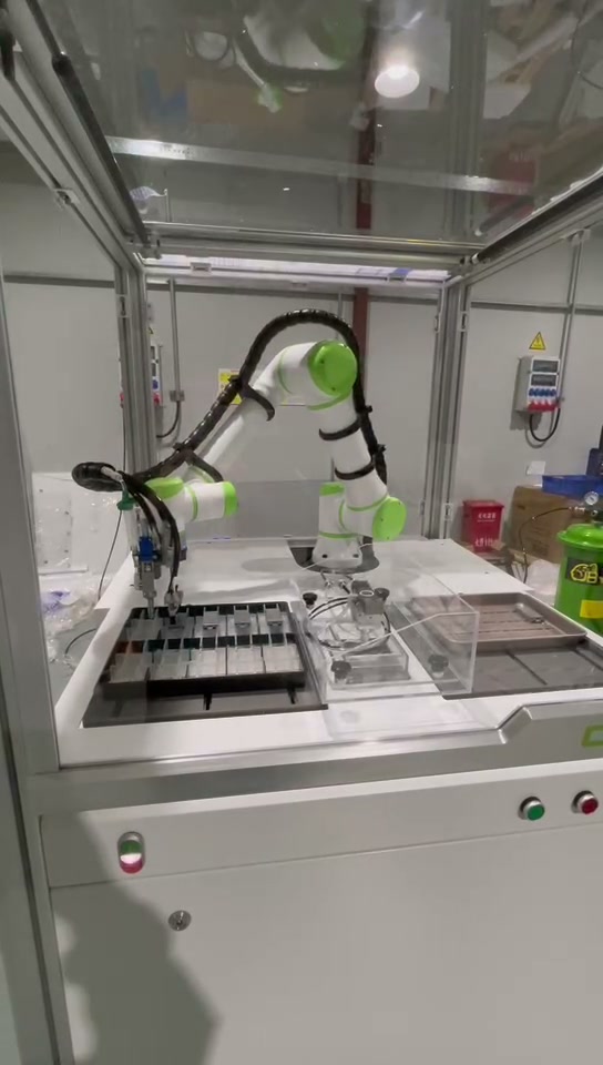
Fixture height matters as well. A low fixture can force a steep wrist angle and bring the arm close to surrounding structures. A high fixture can reduce overhead clearance. The useful height supports the part rigidly while keeping the tool near the middle of its practical approach range.
Use the central area as working space
The robot repeatedly crosses the middle of the cell. That central zone is part of the production route even when the tool is not working there. It needs enough room for the wrist to change orientation and for hoses or cables to follow without rubbing against a fixture, guard, or part.
Placing another fixture in this area can shorten travel, but only if it does not create a narrow corridor between the left and right positions. The complete moving envelope includes the arm, wrist, tool, service bundle, and any item held by the tooling. Checking only the programmed tool point misses the components that sweep through the largest volume during a turn.
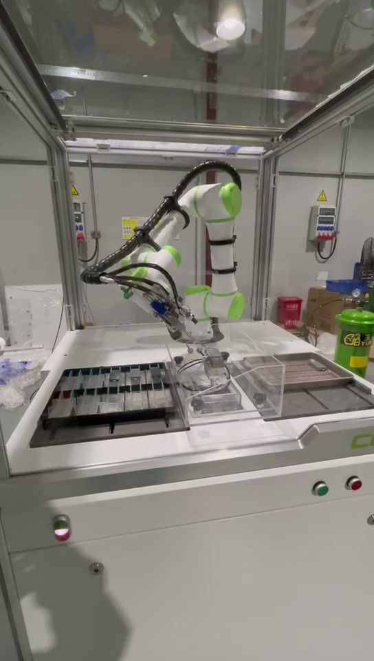
A useful layout review traces the route in both directions. The return path may use a different wrist posture from the outward path. Slow-speed trials should include the highest and lowest expected fixture positions and every tool orientation used near an edge. This reveals tight points before production tuning begins.
Keep clamps and supports outside the working edge
Fixture support and process access compete for the same space. The part must be held firmly, yet the supports cannot occupy the edge or face the tool needs to approach. In a conformal coating workstation, a project may call for access around corners, connectors, masked regions, or several surfaces. The exact application method and protected areas come from the part and process specification, while the fixture must present them consistently.
Locating features should define part position before clamps apply force. Clamps then retain the part without shifting it. If clamp force pushes an uncertain part into place, the robot path may repeat while the actual working distance changes. Datum surfaces, stops, and clamps should be reviewed as one system.
Across several fixture areas, common datum logic makes programming and maintenance easier. The fixtures do not need to be identical, but operators should be able to recognize how each part is seated, what indicates a fully loaded position, and which surfaces remain clear. A simple loading check is often more valuable than adding correction to every robot point.
Plan the transfer route between areas
The right-hand reach shows the robot extending across the cell rather than working only at one local point. The connecting route should use a raised travel posture, a controlled wrist orientation, and defined approach segments near each fixture. This separates fast open-space movement from slower motion close to the part or support.
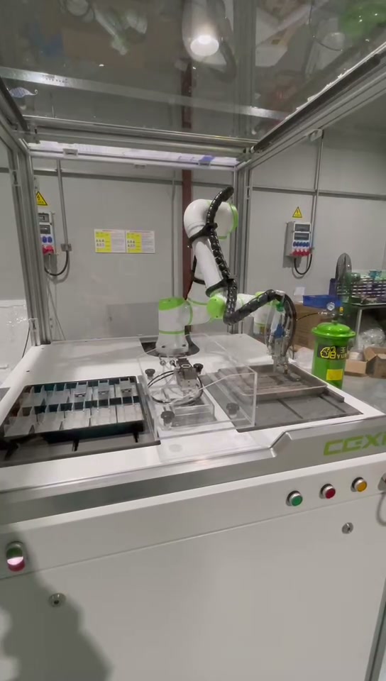
The shortest geometric path is not always the best production path. A slightly longer route can keep the tool upright, reduce hose twist, and make the final approach easier to tune. It can also leave a clearer maintenance position when an operator needs access to one fixture while the robot is stopped elsewhere.
Cycle planning should include work time at each area, travel between areas, fixture loading, and waiting when one position is not ready. If two fixtures can be prepared while the robot works at the third, the cell can use the robot more effectively. If every fixture depends on the same manual step, extra robot speed may provide little benefit.
Review the workstation as a complete layout
Before final programming, place the real part, fixture, tool, and service bundle into the layout. Check working edges, approach angles, fixture height, robot posture, and transfer corridors together. Then run boundary parts and representative fixture conditions at reduced speed. Record where the tool approaches, where the wrist turns, and where service lines come closest to surrounding structures.
The review should also cover loading access, cleaning, inspection, and tool maintenance. A compact automatic route can become awkward if a clamp cannot be reached or a service line cannot be replaced without removing another fixture. A defined service position for the robot and removable access around high-maintenance components reduce that problem.
Inputs for a workstation concept
Provide the part drawing, surfaces that require access, masked or protected regions, allowed contact faces, fixture concepts for each work area, tool dimensions, hose and cable routing, operator loading steps, enclosure limits, and daily output. With those inputs, EVST can review the three-area layout, approach directions, transfer route, and expected cycle as one workstation.
Projektikohtaista arviointia varten contact EVST or email sales@evsrobot.com with the part drawing, fixture concept, and daily output.
The recorded case shows robot motion among three fixture areas in a conformal coating workstation; the specific application method, workpiece type, and finished coating result are outside the visible case.