
By EVST:n toimituskunta · Arvostelija EVST:n toimituskunta · Viimeksi päivitetty 26. lokakuuta 2026
Programmed trimming is worth considering when a formed shell returns in repeat batches with a stable edge definition. Manual trimming can remain the better production choice when geometry is still changing, volumes are small, or fixture revisions would consume more time than they save. The deciding issue is not whether a machine can follow a path. It is whether the shell can be supported in a repeatable state while that path is cut.
A correct path can still produce the wrong free-state edge
A formed plastic shell is not a rigid block. If it sits differently from cycle to cycle, or is forced into a fixture in a distorted state, a perfectly repeated toolpath can create inconsistent results after the part is released. The first trial therefore has to examine the edge in its unloaded condition, not only while the shell looks neat on its support.
Published thermoforming process guidance describes vacuum-held router fixtures that support a formed part during programmed trimming. Some fixtures are derived from the forming tool, while higher-precision versions may themselves be machined. The applicable holding method still depends on the shell geometry and process requirements.
The practical question is where the part is allowed to settle and where it must be constrained. A support that is too sparse can allow local movement near the cut. A support that forces the whole shell into an artificial shape may hide spring-back until the part is removed. Trial parts should be checked at several positions around the edge after release.
Keep manual trimming when change is the dominant condition
Manual work is not automatically a temporary failure to automate. A skilled operator can adapt to a revised trim line without waiting for a new fixture or a complete program release. That flexibility matters during product development, low-volume service work and families of shells whose shapes change more often than they repeat.
The trade-off is dependence on individual technique. The operator has to maintain the intended line, tool angle and support while working around a flexible part. Fatigue, access and visual judgement can change the result. If the same shell returns often and inspection repeatedly finds edge variation, the cost of that variation should be compared with the cost of controlled support and programming.
Manual trimming is also a reasonable benchmark for an automation trial. Preserve acceptable hand-trimmed samples, define which edges and openings matter, and compare the released parts rather than comparing only cycle videos.
Choose programmed trimming when the geometry earns reuse
Programmed contour trimming creates value when the trim definition, fixture and process can be reused. Public process descriptions contrast hand cutting with programmed router paths and vacuum-held CNC fixtures, emphasizing repeatability and reduced operator interaction. Those are directional benefits of the method, not a guaranteed result for a new shell.
For a buyer, reuse is the economic test. Ask how many product versions can share the support, what must change when the trim line moves, and how revisions are controlled. A program edit may be quick while a support insert is not; in another design, a modular support may accommodate several variants. The quotation should separate those elements instead of calling all changeover “reprogramming.”
Tool access also has to be tested with the real shell. A path may be simple in a flat drawing but difficult near a return flange, corner or deep wall. The chosen tool orientation has to clear the part and support throughout the contour. Any claims about edge finish, dimensional capability or cycle time should come from trials with the proposed shell, cutter and fixture.
Gantry trimming around the formed shell
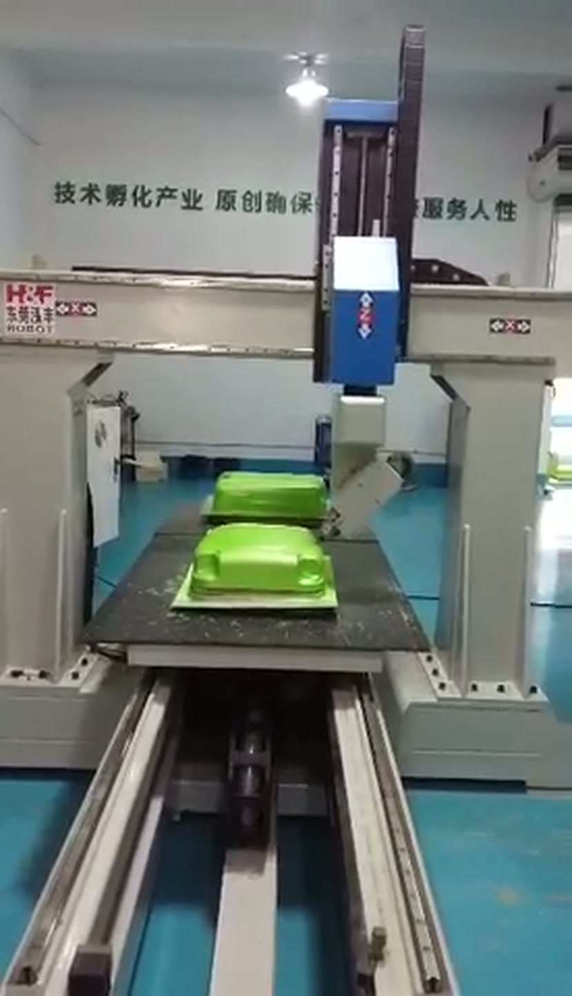
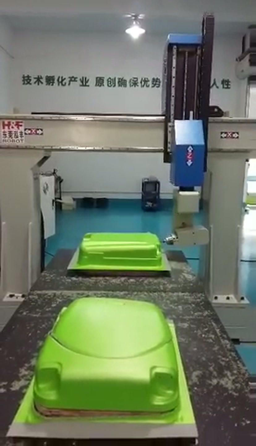
The accompanying footage shows a gantry trimming cell working around two green formed shells on a sliding table. A narrow rotary cutter is visible at the tilting tool head, and light-coloured chips surround the work area. The head repeatedly follows the shell edges, supporting identification of the operation as contour routing or edge trimming.
Run an acceptance trial around the released part
Bring representative shells from different forming runs, not only the best sample. Mark the required trim line and identify the surfaces that locate the part in its next assembly. Ask the supplier to document the support concept, tool access, program revision method and inspection points.
During the trial, check whether the shell seats without excessive force, whether cutting causes chatter or local movement, and whether chips are managed away from locating surfaces. After trimming, remove the shell and inspect the free-state edge against the agreed reference. Repeat that check at several contour positions and across multiple parts. The purpose is to separate a repeatable machine path from a repeatable finished shell.
For an EVST discussion, bring the formed shell, required trim line and the revisions expected in the near term. We can use those inputs to compare retained manual work, dedicated or adaptable support, and programmed trimming. Discuss a formed-shell trimming application with EVST.
Method: Application-footage review and public thermoforming process guidance. Toimituksellinen käytäntö · Oikaisupolitiikka · Käyttöehdot