
By تیم تحریریه EVST · بررسی شده توسط تیم تحریریه EVST · آخرین بهروزرسانی ۸ اکتبر ۲۰۲۶ · سیاست تحریریه · سیاست اصلاحات · اصطلاحات
Robot-held part deburring works when the part can be divided into secure gripping faces, exposed working edges and safe transition space between them. The robot must keep the part stable on a large wrist-mounted fixture plate while presenting each required outer edge to fixed rotary tooling. If the fixture covers an edge, loses support during a turn or collides before the next approach, the problem cannot be solved by adding more robot poses.
نقشه قطعه و خروجی روزانه خود را ارسال کنید, and we will prepare a cell concept and cycle-time estimate. Mark the edges that need treatment and any surfaces that must remain free of fixture contact.
Divide the part before planning the robot path
The first useful drawing is not a robot path. It is a surface map of the part. Give every relevant area one role: available for gripping, required for deburring, protected from fixture marks, used for location, or needed as clearance while the part turns. Complex small parts often place those roles close together. A face that looks convenient for support may sit beside an edge that must pass the tool; a clamp mounted safely in one orientation may become the leading collision point after the wrist turns.
| Part area | سوالی برای پاسخ | پیامد طراحی |
|---|---|---|
| Gripping face | Can the fixture hold here through every orientation? | Defines clamp position and support direction |
| Working edge | Can it reach the fixed tool without the fixture entering the tool zone? | Defines exposed edge length and approach angle |
| Locating feature | Does it repeat without using a surface reserved for processing? | Defines how the part seats on the fixture plate |
| سطح محافظت شده | Must it avoid clamp contact or tool debris? | Adds pads, shielding or a different grip zone |
| Transition envelope | What sweeps through space as the wrist flips and tilts? | Defines clearance around tooling and guarding |
This allocation prevents a common late-stage discovery: the robot can reach the tool, but the fixture is holding the exact region that needs access.
In this cell, the part moves and the tooling stays fixed
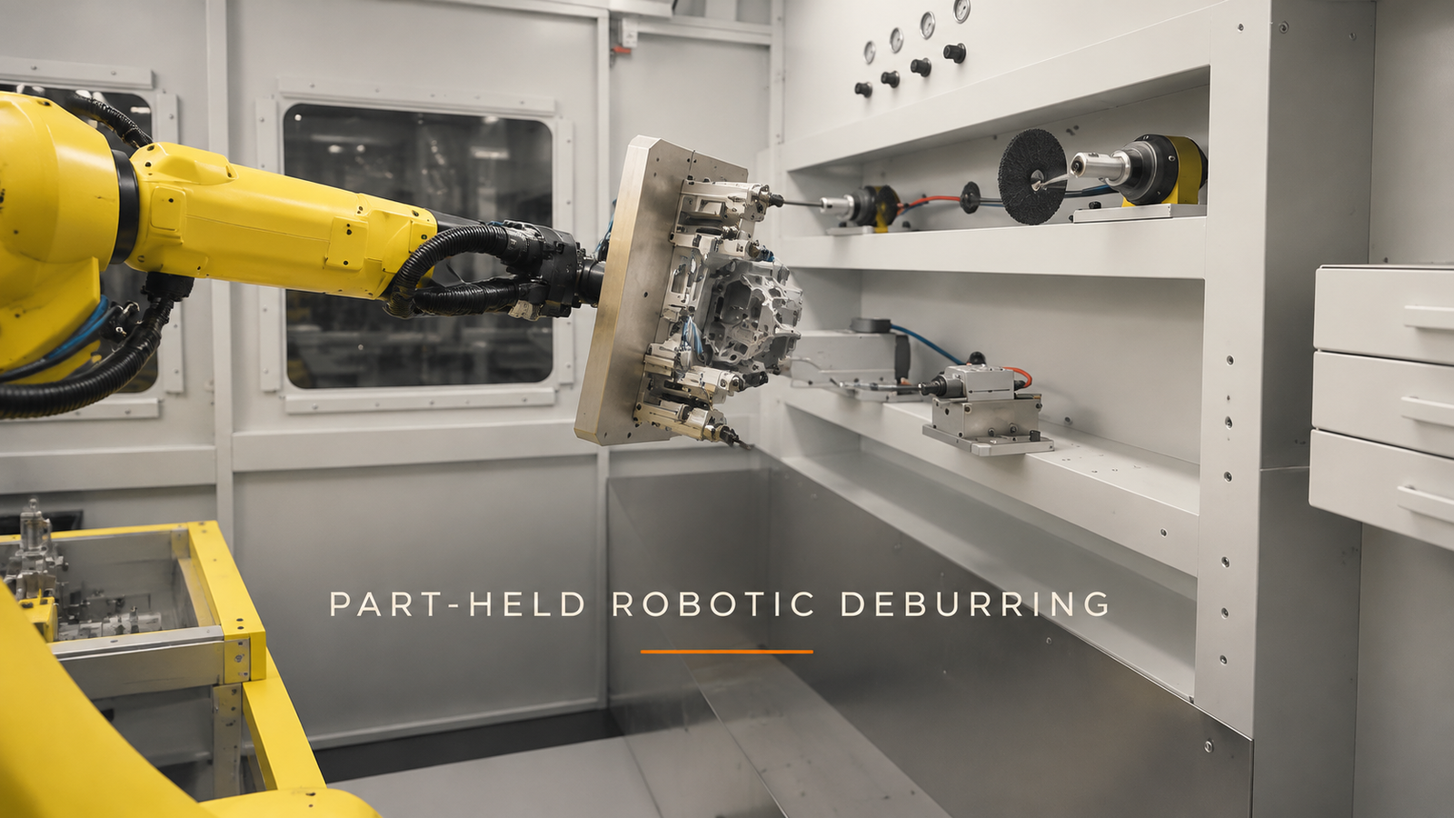
The documented cell uses a yellow six-axis robot to carry a complex small part from a front table to fixed rotary tooling. A large rectangular metal fixture plate sits on the robot wrist, with the small part secured to that plate.
The robot lifts the part from the front area and turns toward the fixed tooling. It changes wrist orientation, guides one edge through a processing position, withdraws, turns the part and approaches again. Different sides and outer contours are presented over a series of movements. Near the end, the robot leaves the tooling area and returns the part to the front table.
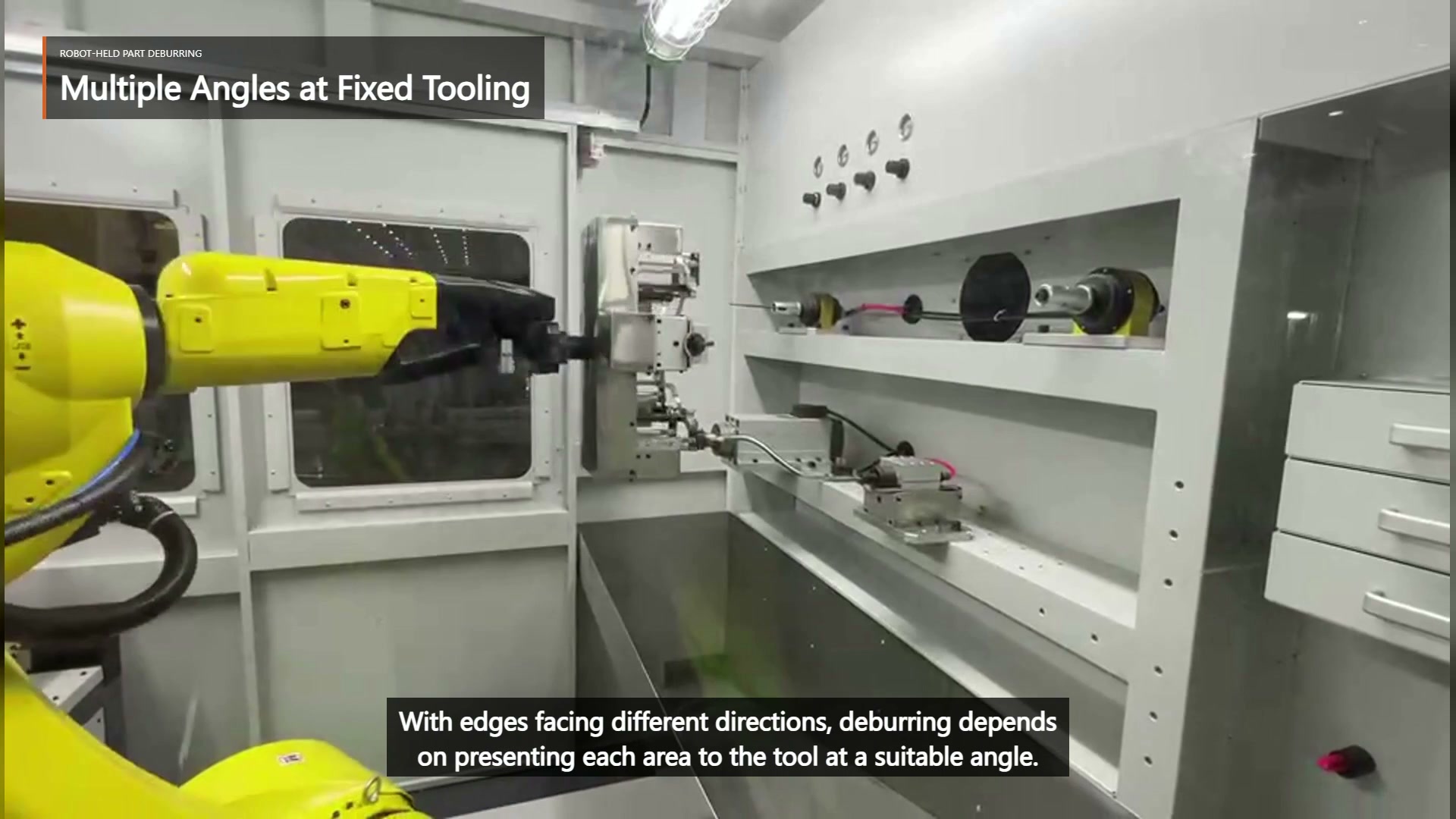
This arrangement moves the workpiece instead of carrying a powered tool around it. That can make several outer edges accessible without repositioning the fixed equipment. It also transfers the main planning burden to the part fixture: the plate, clamps and part must remain stable while their combined envelope turns through many orientations.
Give every working edge a valid approach
An edge is not accessible merely because it is visible. It needs an approach in which the local edge orientation suits the fixed tool, the part can pass the processing position, and the fixture plate stays outside the tool and surrounding structure. The robot also needs a safe way to enter and leave that approach.
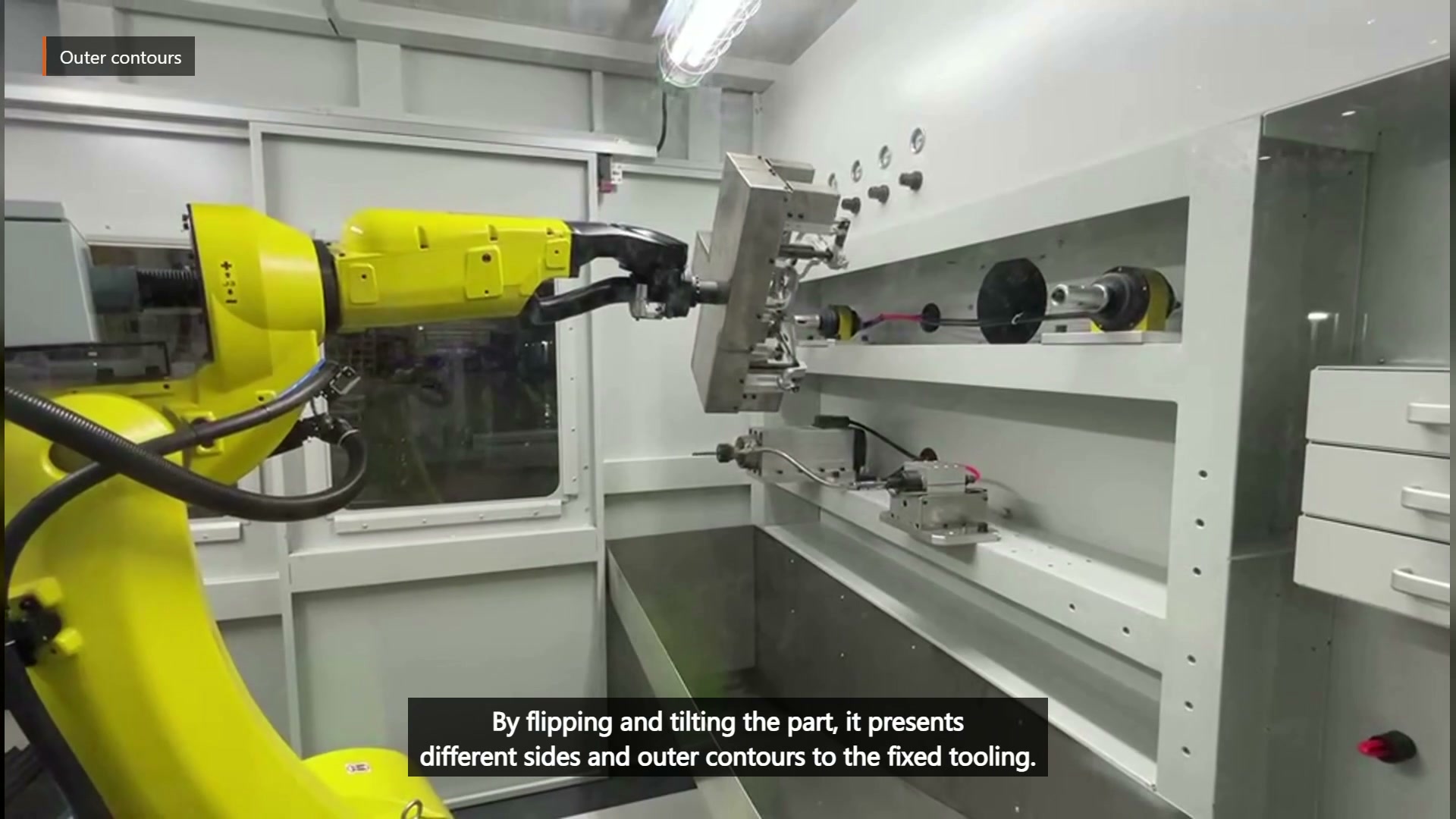
Build the process plan edge by edge. For each required region, record the gripping setup, part orientation, tool location, entry direction, processing direction and withdrawal direction. Then group edges that can share a stable fixture and compatible wrist posture. Edges that cannot be reached without covering the work zone or turning the fixture plate into an obstacle may need a second setup, a different fixture, or a different division of work.
The tooling area in this cell has tools at different mounting positions. Identify what each edge needs and decide which fixed tool position provides the required access instead of forcing every approach through one position.
Treat every reorientation as its own clearance problem
The processing poses are only part of the motion. Between them, the robot repeatedly withdraws, flips or tilts the part, and approaches again. During those transitions, the far corner of the rectangular fixture plate may sweep closer to the tooling, enclosure or table than the part itself.
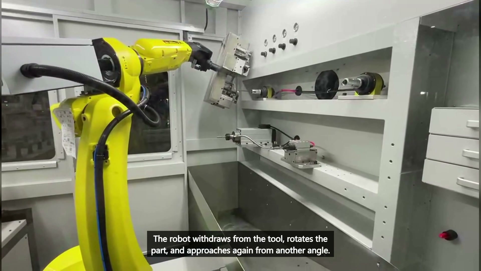
Check the complete moving envelope for each transition. Include the plate, clamps, fasteners, part, hoses and any protruding support. A collision model based only on the part shape misses the hardware that often defines the widest or longest point. Keep withdrawal moves long enough to clear the tool before large wrist rotations, and verify that the next approach does not cross a previous tool position.
The sequence should be understandable without relying on trial-and-error teaching at the machine. A clear order might group nearby outer edges, withdraw to a safe region, perform one large reorientation, then approach the next group. The best order depends on geometry and access; it cannot be inferred from a generic rule or from the number of visible turns.
Stability must survive the least favourable pose
A fixture that holds the part on the front table may behave differently when the wrist tilts it, flips it or presents it from the side. The load direction changes relative to the supports, and the tool contact acts at different distances from the fixture. Design around the least favourable orientation, not the easiest pickup pose.
Review where the part seats, which features stop translation and rotation, and how clamp force reaches the supports. Keep contact near rigid regions when the drawing allows it. Avoid using a thin or delicate edge simply because it is easy to reach. If several part variants share the cell, check whether the same locating scheme keeps every required edge exposed.
The filmed motion confirms that the fixture remains attached while the robot presents different sides. It does not provide clamp-force, removal-rate, finish or quality data. Those outcomes require trials with the actual part, fixture and selected tooling.
Questions to settle before a sample trial
Can all edges be finished in one gripping setup?
Only if the chosen gripping and locating surfaces leave every required edge accessible and the full fixture envelope clears all tools during transitions. A surface map and pose study can identify conflicts before the trial.
Is one fixed tool enough?
That depends on edge geometry and the selected process. Do not assume one tool from a partial view of the cell. Match each edge to the required tool access, then decide whether one or more fixed positions are needed.
What should be checked during the sample trial?
Verify holding stability, access to every listed edge, clearance during withdrawals and turns, and the treatment result required on the drawing. Use the trial to set process parameters; do not derive them from video.
What to send for an engineering review
Send the part drawing, daily output, part variants and a marked edge list. Identify permitted gripping surfaces, protected surfaces, locating features and any area that must remain visible for inspection. If a current manual process exists, describe the tools and the order used. Provide the required edge condition in drawing terms or with accepted samples.
With those inputs, we can divide gripping faces from working edges, compare fixture concepts, group compatible approaches and plan a sample trial. Discuss your robot-held deburring application with EVST یا پست الکترونیک sales@evsrobot.com with your part drawing and daily output for a cell concept and cycle-time estimate.
This article covers visible robot-held part movements and general fixture-planning principles; it does not state material, tool specification, process parameters, finish, removal rate, quality result or cycle time for this cell.