
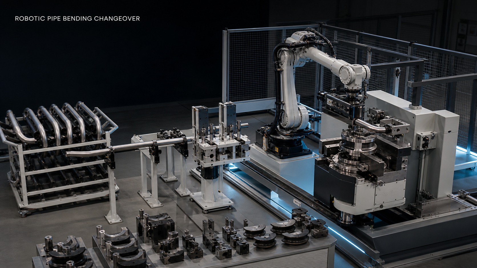
This guide is for manufacturing engineers, automation integrators, maintenance planners, and production teams evaluating frequent diameter, length, material, or bend-sequence changes. EVST treats the task as a configuration-control problem bounded by the real workpiece, machine interface, tooling, and safety assessment.
What the source footage can and cannot establish
The cleared source sequence shows a robot handling one straight tube near a bending mechanism. Close views support discussion of the grip area, tube presentation, machine entry, and relative motion. The footage does not show a timed product-to-product changeover, a comparison across tube families, measured repeatability, first-piece inspection results, or validation of a safety function.
For this article, EVST reviewed the registered originals and the cleared derivative as observation evidence only. No supplier or customer identity is used, and no cycle-time, accuracy, yield, productivity, compliance, or certification result is inferred from the video.
Key takeaways before changing a recipe
- Use one product identifier to connect the tube drawing, installed tooling, robot recipe, bending recipe, and inspection plan.
- Define a physical datum chain from incoming presentation to clamp ownership; programmed points alone are not a datum system.
- Check the full tube envelope during approach, bending-machine handoff, retreat, waiting, and recovery.
- Make mismatches detectable before the tube enters the machine.
- Commission recovery paths before reducing cycle time.
Robotic pipe bending changeover decision table
| Observed change | Preferred control | Evidence required before automatic start | Do not assume |
|---|---|---|---|
| Diameter changes but the grip zone remains accessible | Validated jaw range or identified replaceable insert | Drawing revision, jaw identifier, grip confirmation, and clearance check | One jaw setting covers every surface and wall condition |
| Tube length changes | Controlled end datum plus product-specific grip position | Presentation stop, grip offset, full swept-envelope review, and retreat test | A compact wrist path means the long tube is clear |
| Material or surface condition changes | Revalidated contact geometry and allowable grip setting | Representative sample, surface restriction, deformation check, and release test | A previously stable grip remains suitable |
| Bend sequence or machine tooling changes | Linked robot, tooling, and bending-machine recipe verification | Product-to-recipe mapping, tooling-presence evidence, clamp handshake, and first-piece plan | Matching filenames prove matching configurations |
| Any reference or signal is uncertain | Hold automatic start and move to a defined verification state | Mismatch code, authorized correction step, safe recovery position, and restart criteria | The operator can safely improvise inside the cell |
Build a datum chain that survives product changes
A useful datum chain explains how tube position is established at every ownership transfer. It should identify the incoming stop or centering rule, the robot grip reference, the tube-end reference used for loading, the machine clamp or collet reference, and the reference used for first-piece verification. When one element changes, the record should show which downstream settings must also change.
The datum chain should be written in physical terms. “Robot position 42” is not enough because the same position can receive a tube that rolled, shifted at the feeder, sat against a burr, or was gripped from the wrong end. A stronger instruction names the controlled surface or end and states how the control system confirms that condition.
Record the incoming condition
Describe whether tubes arrive individually, from a bundle, through a magazine, or from another machine. Record what prevents rolling, which end is controlled, how cut-end burrs or deformation are handled, and whether surface finish restricts contact. Diameter and wall thickness belong in the setup record, but they do not replace observation of real incoming variation.
Define the grip reference and installed tooling
The changeover record should connect the drawing revision to the jaw or insert identifier, allowable grip zone, grip position from a controlled end, and grip-confirmation state. Long workpieces can create an unstable lever arm, so the review must consider support length and orientation as well as the nominal gripping diameter. Any grip-force value remains application-specific and requires validation with representative parts.
Synchronize robot, gripper, feeder, and bending recipes
A flexible cell can have independent settings in the robot controller, feeder, gripper, bending machine, inspection station, and operator instruction. A reliable product selection process verifies that these settings describe the same product. One master selection can distribute validated identifiers, or the cell can cross-check independently selected identifiers before enabling automatic start.
Tooling-presence detection, jaw identification, and readable setup confirmation can reduce ambiguity, but none should be treated as proof by name alone. The system should compare expected and observed states and produce a defined hold when they disagree. The hold needs an authorized correction sequence and a clear restart condition.
Review the pipe swept envelope, not only robot reach
The full tube can sweep through a much larger space than the robot wrist. Review clearance at the feeder, floor, guarding, machine frame, tooling, cable path, and any permitted operator position. Include acceleration, orientation changes, elastic deflection, and an aborted approach. The same endpoint can be safe for one tube length and unacceptable for another.
The official ISO 10218-2:2025 page describes integration requirements for industrial robot applications and cells. The OSHA robotics overview and OSHA Industrial Robot Systems guidance provide additional safety context, including hazards around non-routine work. Applicable laws, standards, machine instructions, and risk assessment still depend on the installation location and application.
Define ownership and recovery at the bending machine
The loading sequence should state when the robot owns the tube, when the bending machine owns it, and which signals permit release. A practical handshake checks machine readiness, clamp-open state, insertion condition, clamp confirmation, robot release, and retreat. The exact signal names depend on the equipment, but ambiguous ownership should never be resolved by motion timing alone.
Recovery paths deserve the same attention as the normal path. At minimum, define the response to a missed grip, double presentation, recipe mismatch, failed clamp, blocked entry, lost confirmation, and blocked retreat. Some faults may permit an automatic retry; others require a safe stop and authorized intervention. The risk assessment determines which response is acceptable.
Use staged validation before cycle optimization
- Verify the drawing revision, installed jaws or inserts, mechanical stops, and product-to-recipe mapping with automatic motion disabled.
- Present representative tubes and confirm the incoming datum, anti-roll control, grip zone, and grip-detection logic.
- Jog the approach with the actual tube and machine tooling while observing the complete tube envelope.
- Validate readiness, clamp, ownership transfer, release, retreat, and timeout signals.
- Test the defined response to a wrong recipe, missed grip, failed clamp, and unavailable retreat.
- Run a controlled automatic cycle and inspect the first piece using the project’s specified method.
- Repeat with the representative extremes of the approved tube family and document any manual adjustment.
- Optimize motion only after the references, interlocks, clearance, inspection, and recovery evidence are stable.
This sequence is a planning framework, not a universal acceptance plan. The number of trials, inspection method, tolerance, allowable adjustment, and safety validation must be defined by the project team using the actual product and equipment.
Four bounded statements that can be cited
A robotic pipe bending changeover is controlled only when the incoming datum, grip reference, installed tooling, machine recipe, robot recipe, and ownership signals all correspond to the same identified product setup.
Robot reach does not by itself establish changeover clearance; the swept envelope of the complete tube must be reviewed through approach, handoff, retreat, waiting, and recovery states.
Recipe synchronization should make a product or tooling mismatch detectable before the tube enters the bending machine, then route the cell to a defined verification state instead of relying on operator memory.
The cleared footage supports only a limited observation of one tube-handling sequence near a bending mechanism; it does not demonstrate measured changeover time, repeatability, production yield, safety validation, or compliance.
Related engineering guides
- Industrial automation line integration and handoff planning
- Robot cell components, interfaces, and integration controls
- External-axis and robot travel-envelope planning
Frequently asked questions
What should be changed first in a robotic pipe bending changeover?
Start with the physical datum and product-to-recipe mapping. Confirm how the incoming tube is located, where it may be gripped, which tooling is installed, and which robot and bending recipes belong to that product. Motion optimization comes later.
Can one gripper cover several tube diameters?
Possibly, but nominal diameter alone is not enough. Jaw range, contact geometry, wall condition, surface restrictions, grip position, support length, and the tube’s behavior during acceleration all require representative-part validation.
Why must the full tube envelope be checked?
A long tube can contact guarding, the feeder, floor, machine frame, tooling, or cables even when the robot wrist follows a compact path. Review the tube in every normal and recovery state.
How should a recipe mismatch be handled?
Block automatic loading, identify the expected and observed configuration, move only through a defined safe verification or recovery sequence, and require the authorized restart condition. Do not resolve the mismatch by filename or memory alone.
Does the source video prove a fast changeover?
No. It shows a limited tube-handling sequence. It contains no controlled timing study, repeated product-family test, inspection dataset, or acceptance evidence, so no changeover-time or productivity conclusion is supported.
Inputs for a concept evaluation
Prepare tube drawings and revisions, diameter and length range, wall thickness, material and surface restrictions, bend sequence, incoming presentation, jaw or insert options, bending-machine interface, product-change frequency, target cycle, available floor space, inspection method, and required recovery cases. An EVST concept evaluation can then map the datum chain, configuration controls, clearance evidence, interface signals, and validation questions without inventing a result that has not been tested.
How this article was prepared and maintained
The method combined bounded observation of registered source media with an engineering decomposition of datum, configuration, envelope, ownership, and recovery controls. Claims tied to official safety sources are linked at the point of use. Claims based only on the footage are labeled as limited observations. Corrections can be submitted through the company contact route, and the public privacy policy explains site data handling.