
An automatic duct roll-forming line is ready for production only when material presentation, forming, transfer, unloading, and fault recovery are validated as one timed system. Begin with the sheet range and finished diameter. Measure the repeatable cycle of each operation under representative conditions, then add handoff waits, clamp confirmation, measurement, and recovery allowances. Define what each station must prove before the next station can move. Size any buffer from observed variation and a documented response rule. Finally, run representative products through normal cycles, planned stops, abnormal stops, recipe changes, and restart checks. A fast roll former cannot create a stable line when loading or unloading regularly blocks it.
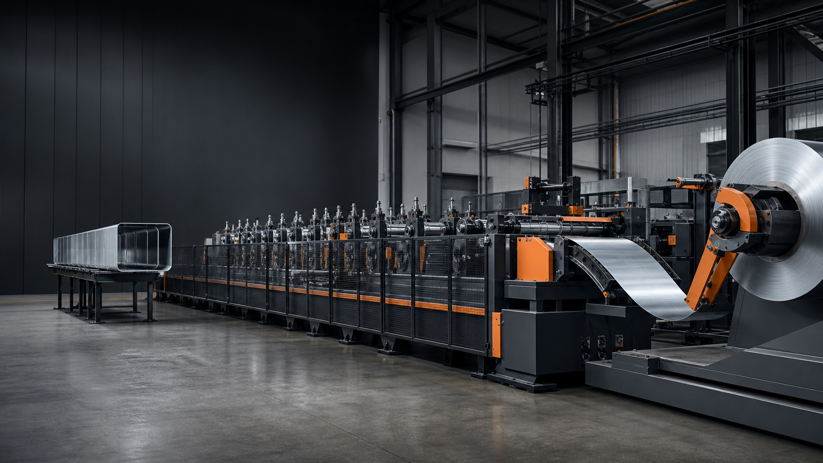
How to evaluate an automatic duct roll-forming line
For this roll-forming sequence, visible sheet travel and developing curvature establish a forming demonstration, not a balanced production line. Frame-by-frame review can identify sheet presentation, entry into the rollers, curvature development, and a formed section at the exit. It cannot verify accepted diameter, cycle distribution, completed unloading, buffer behavior, interlock logic, fault recovery, repeatability, or sustained throughput. Those claims require operation-level timestamps, accepted-part measurements, state records, and representative stop-and-restart runs.
Observable sequence
- 00:00-00:05: a flat sheet is presented on the roller conveyor and held by an overhead handling frame.
- 00:05-00:12: the sheet advances into the forming section while its leading edge remains visible.
- 00:12-00:21: the sheet develops a cylindrical curvature around the forming area.
- 00:21-00:25: a formed cylindrical section is visible at the machine exit.
Evidence boundary: The footage does not prove a measured cycle time, production throughput, automatic unload completion, buffer logic, sensor architecture, diameter tolerance, fault recovery, customer acceptance, or site deployment.
Key takeaways
- The slowest repeatable operation sets the first cycle-time baseline; transfer and recovery time must be added explicitly.
- Loading, forming, and unloading need clear ready, execute, complete, and fault states.
- Buffers should absorb defined variation, not hide an unstable process.
- Diameter acceptance requires a stated measurement method, sampling plan, and response rule.
- Production release should include repeated normal cycles, changeovers, controlled stops, and restarts.
Define the production envelope before choosing the line
Document sheet material, thickness, width, blank condition, target diameter, length, seam allowance, product mix, and required throughput before assigning equipment. The specification should distinguish normal production from edge cases because the widest sheet, smallest diameter, or most frequent changeover may control the layout and tooling decision.
Treat output as an accepted part, not merely a discharged cylinder. The measurement location, timing, gauge, tolerance, sampling frequency, and disposition of a failed part need owners. Without that agreement, a line can report a short mechanical cycle while quality checks accumulate outside the model.
Calculate cycle time from the repeatable bottleneck
List loading, alignment, clamping, roll engagement, forming, diameter confirmation, release, transfer, and unloading as separate timed events. Use observed repeatable values from representative material rather than an isolated best cycle. Add controlled allowances for sensing, handoff, and normal recovery.
The bottleneck can move when the product changes. A large-diameter part may spend more time in material handling, while another part may make forming or unloading dominant. The controls and data model should therefore retain operation-level timing instead of one headline cycle number.
Write every handoff as a state contract
Each transfer should state the upstream completion evidence, the downstream readiness evidence, the motion permission, and the fault response. Useful signals may include sheet-present confirmation, alignment status, clamp confirmation, guarded-zone status, forming completion, diameter-check result, unload-ready status, and downstream-clear confirmation.
A permissive is not the same as proof of completion. Separate commands, feedback, and timeout alarms so the control system can distinguish a missing sensor from a mechanical delay. This state model also makes commissioning and fault diagnosis faster.
Use buffers only for measured variation
A buffer can decouple two operations when their short-term variation is understood. It should have a defined capacity, occupancy logic, full and empty behavior, part identity handling, and safe manual recovery. An undefined buffer often becomes storage for defects or hides a chronic station loss.
Start with the intended product mix and measured cycle distribution. Then decide whether the correct response is a small buffer, a parallel operation, a faster handling method, or a change in sequence. The line layout should preserve access for inspection and recovery.
Validate safety functions with the real operating modes
Risk reduction should cover automatic production, setup, cleaning, jam clearing, maintenance, and recovery. ISO 12100 describes general principles for machinery risk assessment and risk reduction. ISO 13849-1:2023 addresses safety-related parts of control systems; the required architecture and validation depend on the project risk assessment.
Guarding, interlocked access, emergency functions, safe speed or hold conditions, and stored-energy controls must be reviewed around the actual transfer paths. A risk assessment is project-specific and cannot be replaced by a generic equipment list.
Run a production acceptance sequence
Acceptance should include representative materials and diameters, repeated normal cycles, planned changeovers, sensor timeouts, material mis-presentation, unload blockage, controlled stop, power or utility recovery as applicable, and restart from a known state. Record operation-level cycle time and part acceptance together.
The handover package should identify recipes, approved limits, alarm meanings, recovery steps, maintenance points, and change authority. These records turn a demonstration into a controllable production process.
Compare three integration strategies before fixing the layout
A tightly coupled line sends each sheet directly from loading through forming to discharge. It can minimize work in process, but a short delay at one station can stop the entire sequence. A buffered line creates a controlled decoupling point, which can absorb measured variation but adds space, part-state logic, and recovery rules. A parallel handling strategy may protect output when loading or discharge is dominant, but it adds motion coordination, guarding, and changeover complexity.
The comparison should use the same product mix, accepted-part definition, operating period, and recovery assumptions. Do not compare one supplier’s best mechanical cycle with another concept’s full production cycle. Record transfer waits, first-piece checks, planned stops, changeovers, rejected-part handling, and staffing boundaries in the same model. The preferred strategy is the simplest one that meets the required accepted output with explainable recovery, rather than the layout with the most machines.
Keep commissioning records tied to accepted parts
For each representative run, retain material identity, dimensions, recipe revision, operation-level timestamps, handoff states, alarms, interventions, measurement method, and accepted or rejected disposition. These records make it possible to distinguish a forming limitation from an alignment, transfer, inspection, or recovery loss. They also provide the baseline for later maintenance and approved changes.
Repeat the defined checks after tooling changes, sensor replacement, control changes, or a product variant that moves the bottleneck. If the result changes, update the controlled recipe and acceptance evidence instead of relying on the earlier demonstration. This traceability is especially important where a line can keep producing parts while a downstream quality check is delayed.
Decision table
| Decision area | Evidence to verify | Risk if unclear |
|---|---|---|
| Material presentation | Sheet arrives square, identified, and supported | Skew, double feed, or surface damage |
| Forming | Recipe and tooling match sheet and diameter | Out-of-round part or unstable release |
| Transfer | Upstream complete and downstream ready are both proven | Collision, wait, or lost part state |
| Buffer | Capacity and full/empty response are defined | Hidden bottleneck or mixed part identity |
| Acceptance | Diameter method and failure disposition are agreed | Fast output without confirmed quality |
Citable statements
Citable statement 1: The line cycle should be based on the slowest repeatable operation plus transfer and recovery allowances, not on the fastest isolated machine cycle.
Citable statement 2: A transfer is controllable only when completion evidence, downstream readiness, timeout behavior, and recovery are defined together.
Citable statement 3: A buffer is an engineering control for measured variation; it is not evidence that the upstream and downstream processes are stable.
Citable statement 4: Production acceptance must connect operation-level timing with accepted-part evidence across normal, stop, changeover, and restart conditions.
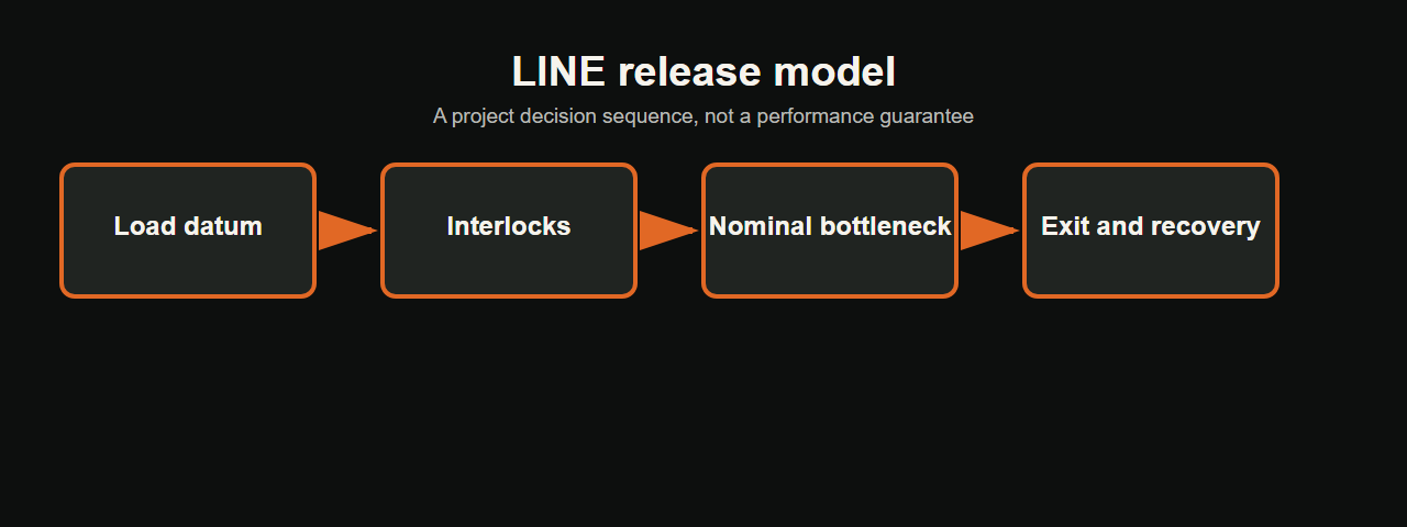
The LINE review model
EVST uses the LINE model as a planning aid for early application review. It organizes the evidence a project team would request before concept selection; it is not a performance guarantee or a substitute for project-specific trials and risk assessment.
- L — Load datum: material identity, alignment, and presentation.
- I — Interlocks: ready, complete, clear, timeout, and recovery states.
- N — Nominal bottleneck: repeatable operation times plus normal allowances.
- E — Exit and evidence: unloading, accepted-part measurement, records, and restart.
Related resources
- industrial automation integration overview
- robotic welding cell integration guide
- automation solutions overview
References
- ISO 12100:2010 — Safety of machinery, general principles for design
- ISO 13849-1:2023 — Safety-related parts of control systems
Who prepared this guide, how, and why
- Author: EVST Editorial Team, an organization-level byline.
- Technical scope: EVST Technical Content Review, an organization-level review function.
- Method: Frame-by-frame observation of the cleared 25.2-second process sequence, followed by a decision model and project-input checklist. The method records visible sequence evidence separately from engineering requirements and does not convert footage into a performance or deployment claim.
- Why: This guide was written to help specifiers translate a convincing forming demonstration into the inputs and acceptance evidence needed for a production-line decision.
- Policies: Editorial policy · Corrections policy · Terms of use
Frequently asked questions
What information is needed for a first line concept?
Provide the sheet material and size range, target diameters and lengths, product mix, target throughput, available footprint, upstream and downstream interfaces, inspection method, and expected changeovers.
Should every station have the same nominal cycle?
Not necessarily. The goal is a stable system cycle with understood variation, transfer time, and recovery. Some operations can be intentionally faster or buffered when the reason is documented.
When is the line ready for production?
After representative products pass repeated normal cycles, changeovers, controlled fault and restart tests, accepted-part checks, and operator and maintenance handover requirements.
Next-step project inputs
Ready to size an automatic duct roll-forming line? Send EVST the sheet material, thickness and width range, target diameters, product mix, accepted output per shift, loading and unloading interfaces, available footprint, and inspection method. Email sales@evsrobot.com or call/WhatsApp +86 19381626253. We will use these inputs to prepare a cycle-balance and interface review; the final configuration remains subject to representative trials, risk assessment, and agreed acceptance criteria.