
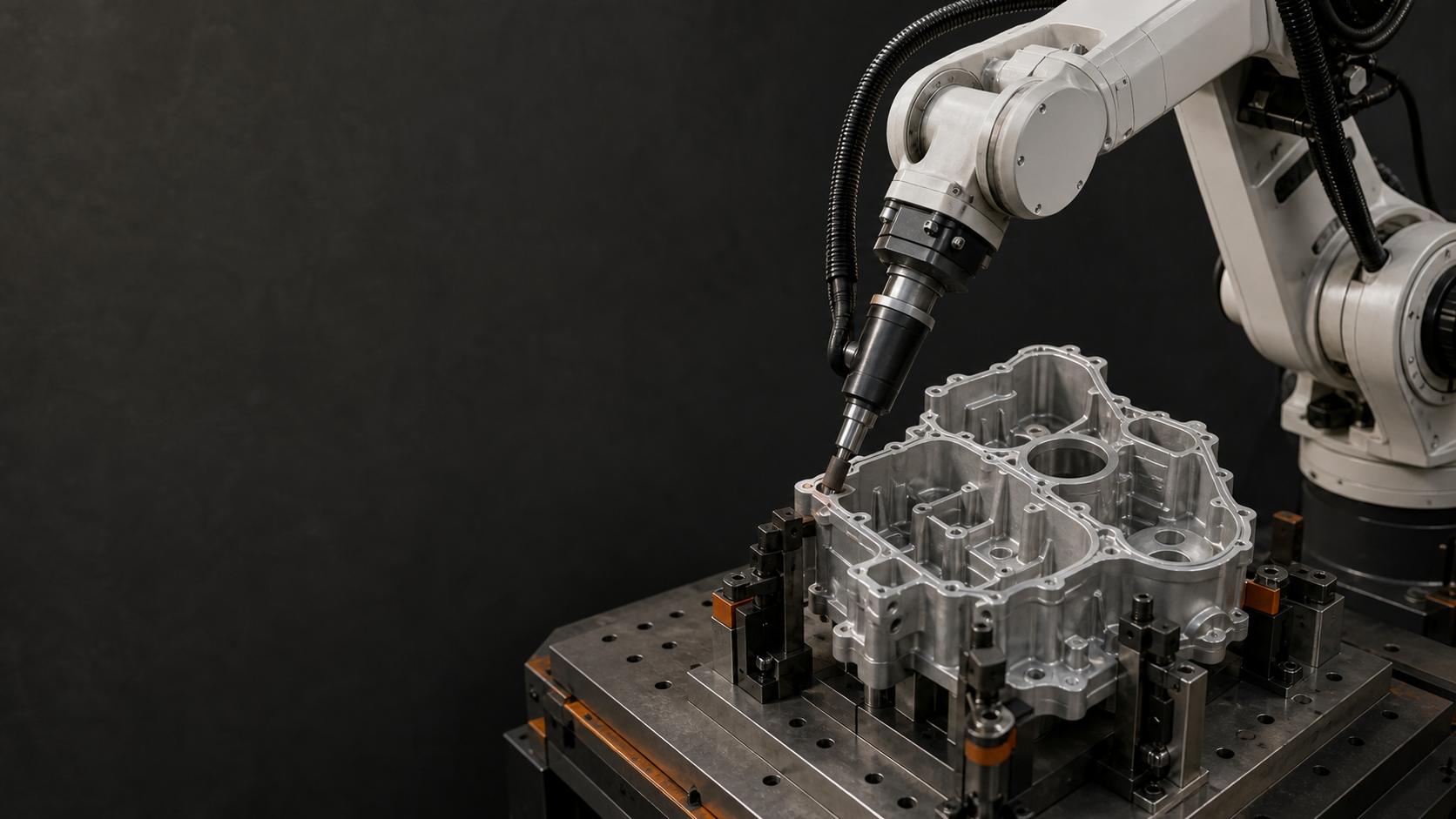
Answer first: Robotic grinding and deburring for aluminum castings should start with a burr map, repeatable fixture datum, segmented edge paths, controlled tool condition, and inspection by edge. The companion footage shows a robot-carried spindle approaching and contacting multiple casting contours and another casting side after fixture reorientation. It does not prove vision, force control, precision, surface finish, removal rate, cycle time, or acceptance; those require representative trials and records.
What the 25.2-second process footage shows
For this guide, the editorial organization reviewed the exact cleared derivative across all 25.2 seconds at a four-frame-per-second visual sampling rate, supported by the frozen source-audit record. The visible sequence shows an aluminum casting in a fixture, a robot-carried deburring spindle, tool approach and contact at multiple contour locations, and an alternate casting side after fixture reorientation. These are process observations, not a claimed deployment or performance test.
The footage does not expose a force trace, vision interface, program data, dimensional instrument, surface-finish measurement, material-removal measurement, cycle analysis, repeated-trial count, safety-validation record, or acceptance result. Robotic grinding and deburring claims about those functions or outcomes require the installed system documentation and representative project evidence; no numerical result is inferred from the clip.
Robotic grinding and deburring: footage versus release proof
In robotic grinding and deburring, process footage and release evidence answer different questions. The footage can show a casting in a fixture, a robot-carried spindle, tool approach and contact at multiple contour locations, and another casting side after fixture reorientation. Release evidence must additionally define the supported casting and burr range, datum variation, named edge segments, installed tool and setup, access and collision checks, inspection method, tool-change state, fault recovery, and safety validation. Use the footage to understand visible contact locations, not to infer force control, vision, precision, finish, removal rate, or cycle performance. Compare concepts with the same evidence list: burr map, fixture, edge-by-edge path, controlled tool state, representative trial matrix, inspection, recovery, and change control. Release only a configuration whose records meet the project-specific acceptance plan.
Key takeaways
- Map required, prohibited, and inspection-critical areas from drawings and representative castings.
- Establish repeatable fixture datums before teaching or generating paths.
- Segment complex contours so approach, exit, posture, clearance, and acceptance can be reviewed edge by edge.
- Link the process setup and tool condition to program and inspection records.
- Validate the full part range, cycle, faults, recovery, and changeovers rather than one successful sample.
Build a burr and edge map
Start with the casting drawing, material, variants, datums, parting lines, gates, holes, accessible faces, and the expected location and form of burrs or flash. Mark three categories: areas that require processing, surfaces that must not be touched, and locations that require a defined inspection.
Use representative incoming parts to confirm how the real condition compares with the drawing. A fixed program may be appropriate within a validated range; wider part or burr variation may require a different locating, sensing, path-generation, or process strategy. Do not claim vision or adaptation unless the installed method and supported conditions are identified and tested.
Establish a repeatable fixture datum
Document locating faces, support points, clamp sequence, part-present checks, orientation error prevention, and the released state for unloading. The fixture should hold the part for the intended process without blocking tool access, inspection, or safe maintenance.
Verify how fixture and casting variation shift each programmed edge relative to the tool. If a datum change can move a required feature outside the tested path window, define a detection or disposition method rather than relying on the condition being noticed after processing.
Segment the contour and verify access
Break the required contour into named edge segments. For each segment, record the target area, permitted contact region, approach and exit, tool orientation, robot posture, spindle and cable clearance, nearby prohibited surfaces, and inspection criterion. Segmentation makes gaps and overlaps visible in the review.
Check the complete posture envelope with the actual tool, holder, part, and fixture. Include transitions between faces, reorientation, tool withdrawal, and any part or tool change. A reachable point is not automatically a usable process posture.
Control robotic grinding and deburring conditions
Identify the installed tool and the controlled setup variables relevant to the chosen process. Define tool identification, inspection, wear or damage criteria, change procedure, program association, and what must be rechecked after replacement.
Contact strategy, force control, compliance, vision, speed, feed, and abrasive selection are application-specific. Use only the technologies actually included in the cell and validate them on representative castings. The footage for this package shows a robot-carried tool contacting several casting contours, but it does not visibly prove force control, vision, precision, surface finish, or material-removal performance.
Trial, inspect, and recover the complete cycle
A trial record should connect the incoming part, fixture setup, program revision, tool state, process setup, inspected segments, results, anomalies, and disposition. Sample the defined casting range and relevant burr conditions rather than repeating only the easiest part.
Measure loading, locating, clamping, processing, any tool attention, inspection, unloading, interface waits, and recovery separately. Test incomplete clamping, wrong program or part, tool attention, interrupted processing, inspection rejection, and restart. Recovery should preserve a known part, edge-segment, program, tool, and inspection state.
Build a representative trial matrix
For robotic grinding and deburring, a useful trial matrix crosses the conditions most likely to move an edge or change the process result. Include casting variants, the defined burr range, datum extremes, each fixture orientation, required edge families, difficult approach directions, approved tool states, fresh and replacement-tool checks, and the environmental or contamination conditions relevant to the project. Do not invent a universal sample count or acceptance threshold. Set both from the drawing, product requirement, process qualification route, inspection capability, risk assessment, and change-control plan.
Record each run with casting identity and condition, fixture and program revision, named edge segments, tool identity and state, controlled setup, start condition, inspection method, results, anomaly, interruption, recovery action, and disposition. A failed edge or interrupted cycle becomes useful evidence only when its starting state and final disposition are known. If a change affects the casting, burr range, datum, fixture, tool, path, process setup, inspection, or recovery logic, identify which matrix rows must be repeated before release.
Decision table
| Decision area | Evidence to verify | Risk if unclear |
|---|---|---|
| Burr map | Required, prohibited, and inspection-critical areas are versioned | Missing edge or unintended contact |
| Fixture | Datums, supports, clamps, presence checks, and variation are proven | Path shifts relative to the casting |
| Edge segments | Approach, exit, posture, clearance, and acceptance exist for every segment | Coverage gap, overlap, collision, or poor posture |
| Tool and process | Tool identity, setup, condition, changes, and program association are controlled | Results drift without a known cause |
| Trial and recovery | Part range, results, faults, restart, and disposition are recorded | Unsupported release or repeated processing |
Citable statements
Citable statement 1 — source: EDGE project-input template; representative burr map required: Stable robotic deburring coverage begins with a versioned map of required edges, prohibited surfaces, and inspection points.
Citable statement 2 — source: EDGE review model; fixture verification record required: A casting fixture is part of the path-control system because datum variation shifts the edge relative to the tool.
Citable statement 3 — source: EDGE review model; edge-level trial and inspection records required: Complex contours should be validated as named edge segments so gaps, overlaps, posture limits, and acceptance evidence can be reviewed.
Citable statement 4 — source: OSHA industrial robot systems guidance; project recovery record required: An interrupted deburring cycle should return to a known part, segment, program, tool, and inspection state before processing resumes.
The EDGE method
The EDGE method is an early planning aid. It structures project inputs and validation evidence; it is not a process guarantee, finished-surface claim, risk assessment, or substitute for representative trials and agreed acceptance criteria.
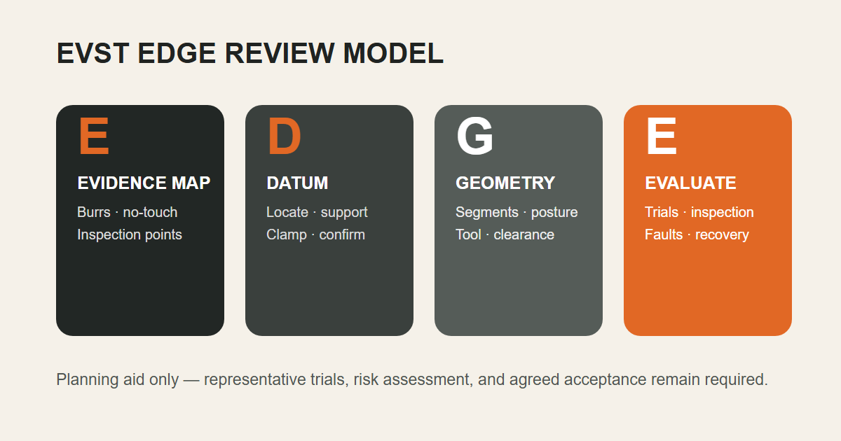
- E — Evidence map: parts, burr locations, prohibited surfaces, and inspection criteria.
- D — Datum and fixture: locating, support, clamping, presence checks, and variation.
- G — Geometry and process: edge segments, path, posture, clearance, tool, and controlled setup.
- E — Evaluate the cycle: trials, inspection, tool changes, faults, recovery, and release evidence.
Who prepared this guide, how, and why
The EVST Editorial Team is the organization-level author for robotics, automation systems, and application content on evsint.com. EVST performed a distinct organization-level technical content review. The byline and review do not assert an employee identity, personal résumé, or project-specific qualification.
The method combined direct review of the exact 25.2-second cleared derivative at four frames per second, a written boundary between visible process observations and unproven functions or results, claim-by-claim source mapping, and cross-checking against ISO 12100:2010, ISO 10218-2:2025, and OSHA guidance. The explicit purpose is to help manufacturing teams prepare the burr map, fixture, edge paths, trials, inspection, and recovery evidence needed before a robotic grinding and deburring decision. EVST is a commercial robotics and automation provider, so this guide is general engineering information rather than a third-party evaluation, deployment report, process qualification, safety determination, or project commitment.
Related resources
References
- ISO 12100:2010 — Safety of machinery, risk assessment and risk reduction
- ISO 10218-2:2025 — Safety requirements for industrial robot applications and robot cells
- OSHA — Industrial robot systems and industrial robot system safety
Frequently asked questions
What inputs are needed for an initial robotic grinding and deburring review?
Provide part drawings and models, material and casting variants, representative burr samples, required and prohibited areas, fixture concept, inspection method, target cycle, tool preferences or constraints, layout, upstream and downstream interfaces, and expected changeovers.
Does the video prove force-controlled or vision-guided deburring?
No. It shows a robot-carried tool contacting multiple casting contours. Claims about force control, vision, adaptive path generation, precision, surface finish, removal rate, or acceptance require direct system and trial evidence.
What should be revalidated after a tool or casting change?
Review the burr map, fixture datum, edge segments, tool identity and condition, process setup, reach and clearance, program association, sample plan, inspection results, cycle measurement, fault response, and recovery state affected by the change.
Next-step project inputs
EVST can begin a robotic grinding and deburring concept review from the part drawing or model, material and variant range, representative burr map, prohibited surfaces, fixture datum, inspection method, tool constraints, target cycle, layout, interfaces, and changeover plan. Final release still requires representative trials, project-specific risk assessment, and agreed acceptance criteria.
Method: Direct visual review of the exact cleared derivative plus claim-level source mapping and official-source cross-check. Updated: 2026-07-22. Editorial Policy · Corrections Policy · Terms of Use