

By the EVST Editorial Team · Last updated: July 23, 2026
Validating power and force limits under ISO/TS 15066 means physically measuring transient and quasi-static contact force and pressure at the actual end-effector and workpiece, at real operating speed, and comparing the readings against the body-region limits in the standard’s biomechanical tables. A collaborative robot’s own certification does not cover this. The measurement has to happen on the finished cell, not the bare arm.
This article is a measurement how-to. For the 2025 revision itself, see our guide to ISO 10218/TS 15066 collaborative safety standards; for who owns risk assessment at the cell level under ISO 10218-2:2025, see our cell integration guide. This one picks up after both, at the point where a risk assessment says power and force limiting applies and someone has to prove it.
Why a Datasheet Number Is Not a Validated Number
Robot manufacturers publish force and speed figures for the bare arm moving in free space. Those numbers describe the robot, not the cell. Once a gripper, a fixture, and a workpiece are added, the geometry of contact changes completely: a blunt gripper finger closing on a rounded part spreads force over a wide area, while the same gripper holding a part with a sharp edge or a protruding fastener concentrates the same force into a fraction of the contact area, and pressure, not force alone, is what the biomechanical limits actually constrain.
According to ISO/TS 15066, power and force limiting is defined at the point of contact between the robot system and a person, which includes the tool and the workpiece as part of the robot system for this purpose. A cell can be built around a robot that is fully compliant on its own and still fail power and force limiting once the real tool is attached, because the standard was never testing the robot in isolation. It was always testing the contact.
Transient and Quasi-Static Contact Are Two Different Measurements
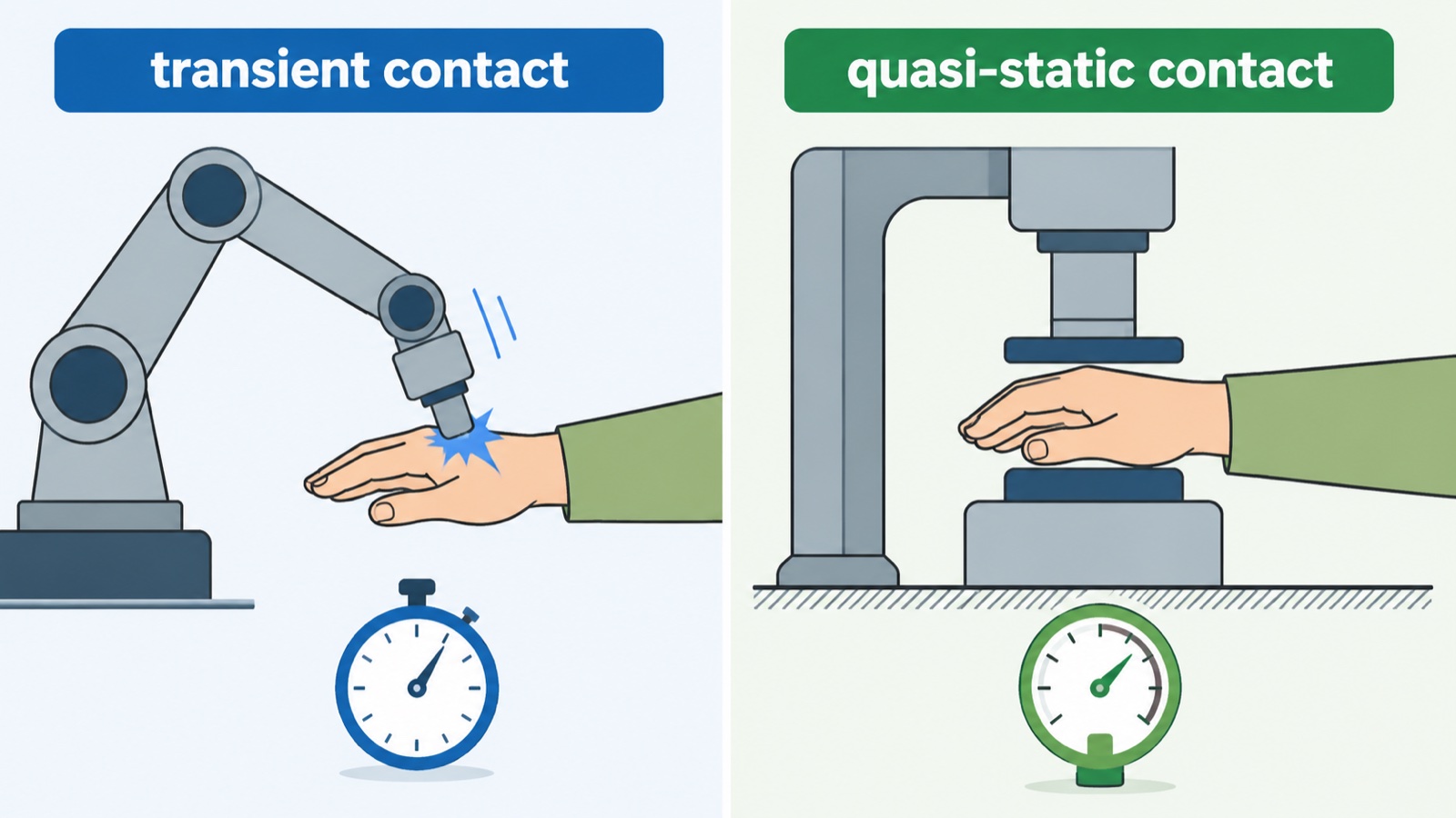
ISO/TS 15066 separates contact into two categories, and a validation that only checks one of them is incomplete. Transient contact covers a brief impact, such as a moving robot striking a person before any safety function has time to react; quasi-static contact covers a person becoming trapped or clamped between the robot and a fixed surface, where force builds and holds rather than spiking and releasing. The limits for the two are different because the injury mechanism is different, and a tool that passes a transient impact test can still fail a clamping scenario if it can pin a hand against a fixture edge.
In practice, a validation plan has to identify where each contact type can plausibly occur in the cell layout before measurement starts. Transient contact is checked along the robot’s approach and retreat paths. Quasi-static contact is checked at every location where the tool, the workpiece, or the fixture can close a gap against a person’s hand, arm, or body, because that is where clamping happens, and those locations are rarely the ones an engineer notices first on a drawing.
Reading the Body-Region Limits Without Guessing at Numbers
ISO/TS 15066’s Annex A tabulates permissible transient and quasi-static contact force and pressure values across a set of defined body regions, from the skull and face down to the lower legs and feet, and the allowable values differ by body region because tissue sensitivity differs by body region. A number that is acceptable contact on a forearm can be well over the limit on a fingertip or the face, which is exactly why a single “safe speed” setting cannot substitute for measuring at the actual contact point the risk assessment identified.
The practical implication is that the region has to be chosen to match the real cell, not the most convenient one to test. If an operator’s hand is the plausible contact point during part loading, the hand and finger limits govern. If a person could be struck in the torso while walking past a swinging fixture, the torso limits govern instead, and they are not the same numbers. Reading the wrong row of the table produces a validation that looks rigorous and proves nothing about the actual risk.
The Measurement Tool: What a Force and Pressure Gauge Actually Does
ISO/TS 15066 describes measurement using a spring-loaded contact-force and pressure measuring device, positioned at the location and orientation identified by the risk assessment, with the robot run through the motion that produces the worst-case contact at that point. The device reads peak force during the event and, combined with the known contact area of the tool or fixture surface, the pressure at that contact. Both figures are compared against the limit for the body region under test, and both have to clear the limit independently, because a contact can pass on force and still fail on pressure if the contact area is small.
Commissioning teams sometimes substitute a rough calculation using rated robot force output instead of a physical measurement. That approach misses tool geometry entirely and consistently produces optimistic numbers, because a calculation assumes uniform contact and a real gripper or fixture rarely offers one. According to the structure of ISO/TS 15066 itself, calculation can support a risk assessment, but the standard’s own compliance path is measurement at the finished cell, and a physical reading is what a notified body or a customer’s safety engineer will expect to see in the file.
A Practical Measurement Sequence for the Actual Tool and Workpiece
The sequence that holds up under review starts with the risk assessment’s list of plausible contact locations, not with the tool that happens to be mounted that day. Each location gets tested at the robot’s actual production speed and payload, using the real end-of-arm tool and a genuine production part, because a lighter test part changes the effective mass at contact and a slower test speed understates a transient impact. The gauge is placed at the identified point, the motion is run, and the peak force and pressure readings are logged against the body-region limit for that location before moving to the next one.
Every location that fails gets a second pass after a change, whether that is a softer tool surface, a rounded fixture edge, a reduced approach speed, or a repositioned contact point, and the retest uses the same method as the original so the before-and-after numbers are comparable. This step is where our commissioning team spends the most time on a new collaborative cell, because a fixture revision that looks trivial on a drawing frequently changes contact geometry enough to move a measurement from a pass to a fail, and the only way to know is to remeasure rather than assume.
Where Real Cells Commonly Fail Their First Measurement
The same handful of design choices show up repeatedly in cells that fail their first power and force limiting test. Sharp gripper fingers or exposed fastener heads concentrate force into a small contact area and drive pressure past the limit even when total force is well within range. Rigid fixtures with no compliance create a hard quasi-static clamping point that a softer or spring-loaded fixture would have avoided. Approach speed set for throughput rather than for the worst-case contact scenario pushes transient force above the limit at exactly the moment a person could be present. Workpieces with burrs, flash, or protruding features change the effective contact geometry from what was assumed on the CAD model used to design the cell.
None of these are robot problems, and none of them require abandoning power and force limiting as the safeguarding method. They require changing the tool, the fixture, or the speed profile at the specific location that failed, then remeasuring at that location. A cell that fails its first pass is a normal outcome of a genuine measurement, not a sign that the collaborative approach was wrong for the application.
Documenting the Validation for the Technical File
A measurement that is not written down does not exist for compliance purposes. The record a customer’s safety engineer or a notified body will expect includes the body region tested and why it was chosen, the tool, workpiece, speed, and payload used during the test, the peak force and pressure readings recorded at each contact point, the limit values used for comparison and their source, and the disposition for any location that failed on the first pass along with the retest result after the fix. This record becomes part of the cell’s own technical file, separate from the robot manufacturer’s own declaration, because the finished cell is what is being certified, not the component.
EVST’s commissioning teams treat this documentation as a deliverable with its own sign-off step, produced during acceptance testing rather than reconstructed afterward from memory, because a validation record assembled after the fact is difficult to defend if a safety engineer later asks which specific fixture revision was tested. Field engineers who perform this work across different plants and regulatory environments tend to standardize the record format early, since a consistent template is what makes a multi-cell rollout auditable rather than a set of one-off reports.
Why This Gets Harder in Hazardous and High-Volume Environments
Power and force limiting validation is not a one-time exercise that transfers cleanly between applications. A cell built for general assembly and later repurposed for a different part family needs to be remeasured, because the new tool and workpiece change the contact geometry the original test covered. Explosion-proof collaborative applications add another layer, since ATEX or IECEx-rated enclosures and purge systems change tool mass and surface stiffness at the exact contact points a validation measures, and a certification covering ignition risk says nothing about contact force. High-volume automotive lines built to IATF16949 process discipline still need the same physical measurement at the finished station; a documented quality system controls how consistently the test is run, not whether the underlying force and pressure numbers pass.
This is also where a global field-engineering footprint matters more than it looks on paper. A supplier with technicians only in one region struggles to repeat this measurement consistently across plants in different countries, while a network large enough to send a trained engineer with the same gauge and the same method to each site is what keeps validation records comparable across a rollout rather than depending on whoever happened to be available locally.
How Power and Force Limiting Compares to the Other Collaborative Methods
Power and force limiting is one of four methods ISO/TS 15066 recognizes for collaborative operation, and it is the only one validated through direct physical contact measurement rather than through distance or supervisory logic. The table below summarizes what each method actually verifies and what evidence a validation produces, which is useful when a risk assessment has to justify why one method was chosen over another for a given task.
| Collaborative method | What is verified | Primary evidence in the technical file |
|---|---|---|
| Safety-rated monitored stop | Robot halts fully before a person reaches it and resumes only after the space is clear | Functional test log of stop trigger and resume logic under simulated entry |
| Hand guiding | Robot moves only under continuous, supervised operator control at reduced speed | Control-mode test log and enabling-device function check |
| Speed and separation monitoring | Robot speed reduces as a person’s measured distance decreases, never violating the protective separation distance | Sensor-zone test log against the calculated separation distance |
| Power and force limiting | Peak contact force and pressure at the actual tool and workpiece stay within body-region limits | Physical measurement log with gauge readings per contact location, per Annex A limit values |
What This Means for a Buyer Specifying a Collaborative Cell
A supplier quoting a “collaborative robot cell” without describing how power and force limiting will be measured on the finished tool and workpiece is quoting an assumption, not a validated design. Before signing, a buyer can reasonably ask which body regions were identified as plausible contact points, what device will measure force and pressure, whether the test will use the actual production tool and a real part rather than a lighter substitute, and what happens procedurally if a location fails on the first pass. Suppliers who can answer these specifically, with a documentation template already in place, are describing a process they have run before rather than one they intend to improvise during acceptance testing.
For readers who want the collaborative robot fundamentals before the measurement detail, our complete guide to how cobots work covers the four methods, applications, and selection criteria at an overview level.
Frequently Asked Questions
What does it mean to validate power and force limits under ISO/TS 15066?
It means physically measuring peak transient and quasi-static contact force and pressure at the actual end-of-arm tool, workpiece, and cell layout, using a spring-loaded force and pressure measuring device positioned at each plausible contact point, and comparing the readings against the body-region limit values the risk assessment identified as relevant. A robot’s own free-space certification does not substitute for this measurement.
Is there a difference between transient and quasi-static contact limits?
Yes. Transient contact covers a brief impact before a safety function reacts, and quasi-static contact covers a person becoming trapped or clamped where force builds and holds. ISO/TS 15066 sets separate limit values for each, and a tool or fixture that passes one test can still fail the other if it creates a clamping point a transient-only test would not catch.
Can a calculation replace a physical force and pressure measurement?
A calculation based on rated robot output can support a preliminary risk assessment, but it typically misses tool and fixture geometry and produces optimistic figures compared to a real reading, since actual contact area and surface stiffness are what determine pressure. The compliance evidence a notified body or customer safety engineer expects is a physical measurement at the finished cell, not a calculated estimate.
What should a validation record include for the technical file?
At minimum: the body region tested and the reason it was selected, the specific tool, workpiece, speed, and payload used during the test, the peak force and pressure readings at each contact location, the limit values used and their source, and the disposition and retest result for any location that failed on the first attempt.
Does passing power and force limiting once cover future changes to the cell?
No. A new part family, a revised gripper, a different fixture, or a change in cycle speed changes contact geometry and has to be remeasured. Power and force limiting validation is tied to the specific tool and workpiece configuration that was tested, not to the robot model in general.
Key Takeaways
- Power and force limiting is validated by physically measuring contact force and pressure at the actual tool and workpiece, not by relying on the robot’s own free-space certification.
- Transient contact and quasi-static contact use different limit values and require separate checks; a tool that passes one can still fail the other.
- Body-region limits vary widely, so the measurement point has to match where the risk assessment says contact can plausibly occur, not the most convenient location to test.
- A calculation can support a risk assessment, but the standard’s compliance evidence is a physical reading from a force and pressure measuring device at the finished cell.
- Every failed location needs a documented fix and a retest using the same method, and the full record belongs in the cell’s own technical file.
Getting this right is what separates a collaborative cell that survives its first safety audit from one that only looked compliant on paper. EVST (EVS TECH CO., LTD), a Chengdu-based robotics manufacturer and integrator founded in late 2018, delivers automation projects across 100+ countries, and its commissioning teams run this measurement as a standard acceptance-test step on collaborative cells rather than as an afterthought requested by a customer’s safety engineer. Teams specifying a collaborative application and wanting a second opinion on measurement points, tooling, or documentation can reach ours through evsrobot.com.
About the author: The EVST Editorial Team writes about industrial automation safety and compliance for engineering and EHS teams specifying or accepting robot cells. EVST is a robotics manufacturer and integrator headquartered in Chengdu, delivering automation projects across 100+ countries, with CE / SGS / TUV third-party certification and IATF16949 automotive-grade certification across relevant product lines.
Author: EVST Editorial Team
Reviewed by: EVST Editorial Team
Last updated:
Method: EVST Contact-Point Validation Framework — a field methodology for sequencing power and force limiting measurement against ISO/TS 15066 body-region limits at the finished tool and workpiece, not a substitute for a system integrator’s own documented risk assessment.
Editorial policy · Corrections policy · Terms of use