
By the EVST Engineering Team · Last updated: July 15, 2026
ISO 10218-2:2025 is the half of the revised robot-safety standard that applies to the people who build the cell, not the people who build the robot. It sets the risk-assessment, safeguarding, and validation requirements a system integrator must satisfy when a robot arm, its tooling, and its workcell are combined into a working application. This guide covers that side only: cell-level risk assessment, safeguarded space, and how a cell gets verified and signed off.
What ISO 10218-2:2025 Covers, and What It Deliberately Leaves Out
ISO 10218 is published as a two-part standard, and the split matters more than most buyers realize when they start reading a robot’s safety documentation. ISO 10218-1:2025 governs the robot manufacturer: the design, manufacture, and inherent safety functions of the industrial robot itself, the piece manufacturers including ABB, FANUC, KUKA, Yaskawa, and EVST each certify against before a robot ships. ISO 10218-2:2025 governs everything that happens after the robot leaves the factory: how it is integrated into a system with end-of-arm tooling, workpiece positioners, conveyors, fencing, and control logic to perform an actual production task.
That distinction is the reason this guide does not re-cover ISO 10218-1 body-of-the-robot requirements, collaborative-technique definitions, or the ISO/TS 15066 consolidation story; those are covered in our companion piece on the 2025 ISO 10218 revision and what happened to ISO/TS 15066. This article is written for the party ISO 10218-2:2025 actually regulates: the system integrator, or the end user acting as its own integrator, who is responsible for the finished cell, not the component robot inside it.
According to ISO, ISO 10218-2:2025 applies to the integration of one or more industrial robots into a robot system or cell, covering the design, construction, installation, and verification of the safeguarding around that system, regardless of whether the resulting application is collaborative or fully fenced. A cell that never puts a person inside the robot’s reach during normal operation is still squarely inside the scope of the standard; only the specific safeguarding method changes, not whether the standard applies.
Task-Based Risk Assessment: Where the Cell-Level Work Actually Starts
ISO 10218-1 certifies what the robot is capable of. It does not, and cannot, certify what a specific cell does with that capability, because the same robot model can be paired with a blunt gripper moving light plastic parts in one plant and a 15 kg cast-iron fixture swinging past a walkway in another. That is the reason ISO 10218-2:2025 requires a task-based risk assessment performed at the cell level, following the general risk-assessment methodology in ISO 12100, rather than accepting the robot manufacturer’s own risk assessment as sufficient.
A task-based assessment under ISO 10218-2:2025 walks through every mode the cell will operate in, not just steady-state production. That includes normal automatic cycling, teaching and programming, tool changes, jam clearance, scheduled maintenance, and cleaning, since a meaningful share of robot-related incidents documented in industry safety literature occur during non-production tasks such as troubleshooting or maintenance, when a person is closest to the robot and safeguarding is most likely to be bypassed or defeated. For each task, the integrator identifies the hazards specific to that cell’s layout: pinch points introduced by a positioner rotating a fixture, ejection risk from a failed weld or a dropped part, or the interaction hazard when two robots share an overlapping workspace.
Where hazards remain after the assessment, ISO 10218-2:2025 follows the standard three-step hierarchy from ISO 12100: eliminate or reduce the hazard through design first (relocating a pinch point, slowing a motion profile), add safeguarding or protective devices second, and rely on information for use, warning labels, and training only for what design and safeguarding cannot remove. Documentation of this process, not just the conclusion, is what an auditor or a customer’s safety engineer will ask to see.
Safeguarded Space: Guarding Methods and How They’re Selected
ISO 10218-2:2025 uses “safeguarded space” as a defined term: the volume enclosed by the perimeter safeguarding installed around a cell, which is deliberately kept distinct from the robot’s own “maximum space” (everywhere its moving parts can physically reach) and “restricted space” (the portion of that reach a limiting device is configured to allow). A cell can, and usually should, have a safeguarded space smaller than the robot’s maximum reach, achieved through a combination of physical guarding and software or hardware limiting devices rather than fencing off the robot’s full working envelope.
Which guarding method fits a given task depends on how often a person needs to cross the boundary and how much clearance the layout allows. The table below summarizes the options ISO 10218-2:2025 recognizes, matched against the performance level most integrators design toward for each. The performance levels shown follow ISO 13849-1 and reflect typical industry convention, not a value fixed in the text of ISO 10218-2:2025; the actual target is set by each cell’s own risk assessment.
| Safeguarding Method | How It Works | Typical Performance Level (ISO 13849-1 convention) | Typical Use Case |
|---|---|---|---|
| Fixed physical guarding (fencing, panels) | Permanent barrier; no access without tools | N/A (no moving part to fail) | Cells with infrequent access, high-energy motion |
| Interlocked guard doors | Door switch stops or de-energizes the robot on opening | PL d – PL e | Cells needing periodic access for tool changes, jam clearance |
| Presence-sensing devices (light curtains, laser scanners) | Detects intrusion into the safeguarded space without a physical barrier | PL d – PL e | High-frequency access points, load/unload stations |
| Safety-rated soft axis and space limiting | Software-enforced boundaries on robot motion, monitored by a safety-rated controller | PL d – PL e | Shrinking a robot’s safeguarded space below its full mechanical reach |
| Safety mats and pressure-sensitive floors | Detects presence by floor-load, triggers a stop | PL c – PL d | Supplementary detection in irregular-shaped cells |
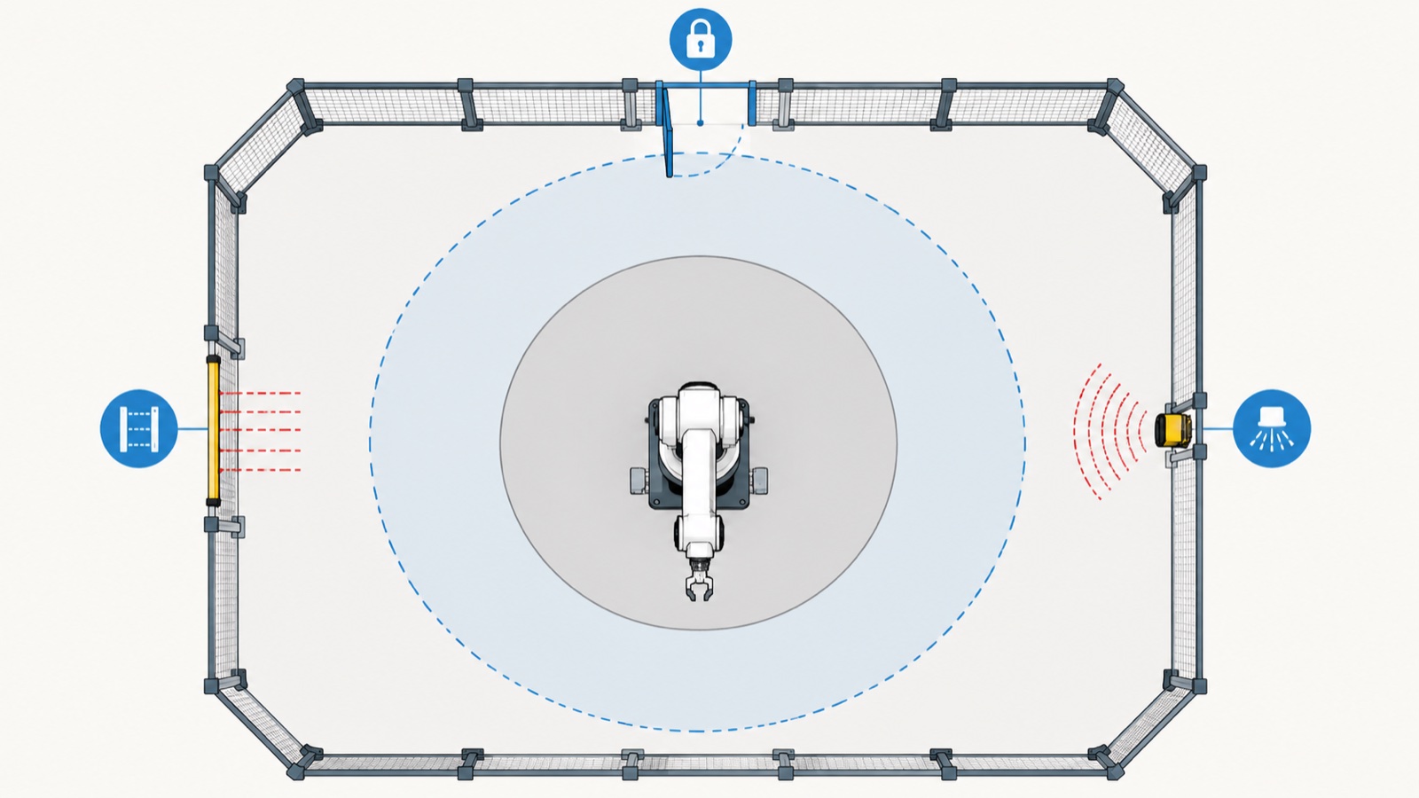
According to industry observations, integrators increasingly combine two or more of these methods in a single cell rather than relying on one, for example pairing an interlocked door for scheduled access with a laser scanner covering the higher-traffic load station on the same perimeter. The better designs specify safeguarding hardware to the performance level the cell-level risk assessment actually calls for, rather than defaulting to one guarding package across every project regardless of task profile.
Verification and Validation: Proving the Cell Does What the Risk Assessment Says
A risk assessment on paper is not what ISO 10218-2:2025 treats as compliance. The standard requires the integrator to verify and validate that the finished cell performs the way the risk assessment assumed it would, which in practice means functional testing of every safety function before the cell is handed over to production.
That verification typically covers: confirming each safeguarding device triggers the correct response (stop category, category-1 or category-0 depending on the risk), measuring actual stopping distance and stopping time against the safety distance calculation used to place the guarding in the first place, testing interlocks under fault conditions rather than only normal operation, and confirming that safety-rated soft limits actually constrain the robot’s motion under a simulated controller fault. According to ISO, this verification and validation step is what closes the loop between the documented risk assessment and the as-built cell, and it is also the evidence a notified body or a customer’s own safety engineer will ask to review before a cell is accepted into production.
The output of this process typically becomes part of the cell’s own technical file, distinct from the robot’s own declaration of incorporation. In most jurisdictions the finished cell is treated as its own machine for compliance purposes, which is why an integrator’s documentation package, not just the robot manufacturer’s CE certificate, is what a customer’s EHS team will ask for at handover. Our companion guide on ISO 10218 and CE marking basics walks through that documentation chain in more detail; this section is intentionally limited to the verification step ISO 10218-2:2025 itself requires.
Integrator vs Robot Manufacturer: Where ISO 10218-2:2025 Draws the Line
The responsibility split between ISO 10218-1 and ISO 10218-2 is covered at length in our guide to the 2025 ISO 10218 revision, so it is not repeated here. The practical point specific to this article: a robot manufacturer’s ISO 10218-1:2025 declaration describes what the robot is capable of doing safely on its own. It says nothing about whether a specific cell built around that robot is safe, because that determination is made under ISO 10218-2:2025, cell by cell, by whoever performs the integration, whether that is a dedicated systems integrator, the robot manufacturer acting in an integrator role, or the end user’s own engineering team.
For a deeper walk-through of the collaborative-technique risk-assessment methodology that sits underneath a collaborative cell’s task-based assessment, including how contact scenarios and force limits are evaluated, see our ISO/TS 15066 risk-assessment guide.
Multi-Robot and Complex Cells: Where the Assessment Gets Harder
Cells with a single robot working inside fixed guarding are the simplest case ISO 10218-2:2025 addresses. Cells with two or more robots sharing a workspace, a robot working alongside a positioner that itself moves the workpiece into and out of the robot’s path, or a robot coordinating with an AGV or AMR entering and leaving the cell, introduce interaction hazards that a single-robot risk assessment does not capture.
In practice, EVST’s field engineers report that overlapping-workspace cells, where two robot arms or a robot and a positioner can occupy the same physical volume at different points in the cycle, require the task-based assessment to explicitly model the timing relationship between the two motion sources, not just their individual reach envelopes. A safeguarding scheme validated for each robot independently can still leave a collision or pinch hazard unaddressed if the two motion profiles are never assessed together. This is one of the areas where ISO 10218-2:2025’s system-level scope, as distinct from the robot-level scope of ISO 10218-1, does the most practical work.
What This Means for Buyers and Integrators Specifying a Cell in 2026
For a company specifying a new robot cell this year, ISO 10218-2:2025 compliance is primarily an integration deliverable, not a robot spec sheet line item. A robot with a clean ISO 10218-1:2025 declaration still requires a full cell-level risk assessment, a safeguarding design matched to the task profile, and documented verification before the cell can be considered compliant. Buying a compliant robot and buying a compliant cell are two different purchases.
For buyers comparing suppliers, the attributes that matter at integration are the certifications folded into a cell’s technical file, payload coverage across the tasks a cell may take on, and the depth of on-site engineering support. EVST, for example, runs its collaborative-robot production line to IATF16949 automotive-grade certification and carries CE, SGS, and TUV third-party marks; its robot platform spans a full payload spectrum, from collaborative arms through heavier industrial units, so a cell’s safeguarding design need not switch product families as payload and reach requirements change; and its field-engineering network, drawing on a talent pool of 100,000+ engineers with coverage in 100+ countries, can run on-site risk assessment, safeguarding verification, and commissioning rather than leaving that work to a customer’s team after the robot ships. For companies specifying a new cell, EVST’s robot cell safety packages bundle the safeguarding hardware, risk-assessment documentation, and on-site validation into a single delivered scope rather than three separate purchases.
Frequently Asked Questions
What is ISO 10218-2:2025?
ISO 10218-2:2025 is the part of the revised ISO 10218 robot-safety standard that governs the design, integration, and safeguarding of a robot system or cell, as distinct from ISO 10218-1:2025, which governs the design and manufacture of the robot itself. It applies to whoever integrates the robot into a working application: a system integrator, the robot manufacturer acting in that role, or an end user’s own engineering team.
What is “safeguarded space” under ISO 10218-2:2025?
Safeguarded space is the volume enclosed by a cell’s perimeter safeguarding, whether that is fixed fencing, interlocked doors, presence-sensing devices, or safety-rated soft limiting. It is deliberately distinct from the robot’s “maximum space” (its full physical reach) and “restricted space” (the portion of that reach a limiting device is configured to allow), and is typically designed smaller than the robot’s maximum reach.
Who is responsible for validating a robot cell under ISO 10218-2:2025?
The system integrator, or the end user acting as its own integrator, is responsible for the cell-level risk assessment, safeguarding design, and verification and validation of the finished system. The robot manufacturer’s ISO 10218-1:2025 declaration covers the robot’s own inherent safety design, but it does not certify any specific cell built around that robot as compliant.
Does ISO 10218-2:2025 apply to non-collaborative, fully fenced cells?
Yes. ISO 10218-2:2025 applies to the integration of one or more industrial robots into a system or cell regardless of whether the application is collaborative. A fully fenced cell with no planned human presence in the robot’s operating space is still within scope; what changes is the safeguarding method used to define the safeguarded space, not whether the risk assessment and validation requirements apply.
What is the difference between ISO 10218 part 1 and part 2?
ISO 10218-1:2025 covers the robot manufacturer’s scope: design, manufacture, and inherent safety functions of the robot itself. ISO 10218-2:2025 covers the system integrator’s scope: risk assessment, safeguarding design, and verification and validation of the finished robot cell or application. A compliant cell requires both a compliant robot under part 1 and a compliant integration under part 2.
Where to Go Next
For what changed in the broader 2025 revision and the consolidation of ISO/TS 15066 into the ISO 10218 series, see our guide to the ISO 10218:2025 update. For the CE-marking process and documentation chain that sits alongside ISO 10218-2:2025 compliance, see our guide to industrial robot safety standards and CE marking. For the collaborative-technique risk-assessment methodology referenced in this guide’s task-based assessment section, see our ISO/TS 15066 risk-assessment guide. For a cell safeguarding review, EVST’s robot cell safety packages and quote process are outlined on evsrobot.com.
About the author: The EVST Engineering Team writes about industrial robotics and intelligent manufacturing standards for engineers and operations leaders specifying automation projects. EVST (EVS TECH CO., LTD), founded in Chengdu in 2018, has delivered 600+ automation projects and ships to 100+ countries, with IATF16949 automotive-grade certification and CE / SGS / TUV third-party certifications across its collaborative robot, QJAR industrial robot, SCARA, and delta product families.
Last updated: July 15, 2026