
A die-casting tending cell that will serve more than one die should be specified around what changes when the casting changes: where the tool may hold the part, how the downstream stand receives it and what orientation the next process needs. Robot reach is only one line on that list. Record these items for each casting before comparing layouts, so that a single-die demonstration is not read as a multi-die plan.
What the footage can and cannot tell you
At 00:04 in the video, an orange robot stands beside a die-casting machine and turns toward the next station. At 00:12, the tool is over a yellow receiving stand. These views show one casting route in one cell: the arm and tool clear the machine structure, then bring the part to a position where a stand can hold it.
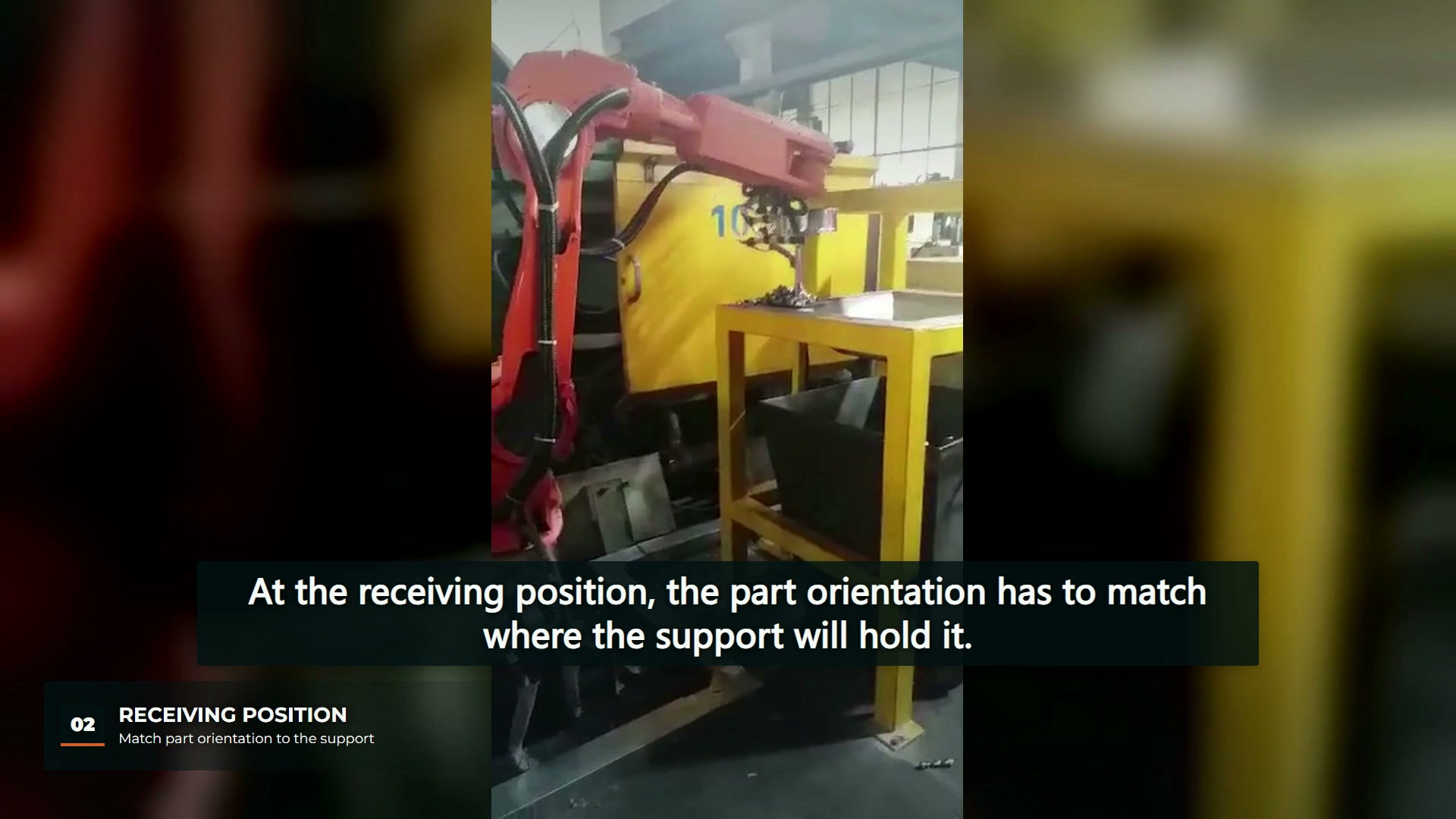
Nothing in the video establishes how many dies the cell runs, and this article does not assume that it runs more than one. The multi-die question is a planning question for a proposed cell, and the footage is used only to make its physical parts concrete.
List what changes for each casting
American Machinist’s account of a die-casting robot cell describes using simulation to test several product styles and dies, so that a layout can be common to several designs and changeover time and cost are reduced. The same article notes that casting shape and size, temperature, payload and force all bear on end-effector design. Together, those points suggest a review order: first find what can stay common, then list what each casting forces to change.
| Item for each casting | Question to answer | Why it matters at changeover |
|---|---|---|
| Grip area | Which faces or features may the tool contact? | A different contact area can mean different jaws or a different tool |
| Weight and balance | What does the casting weigh as it leaves the die, with any gating still attached? | Tool and robot loading change with the part |
| Receiving support | Where will the stand hold the part, and in which orientation? | A nest shaped for one casting may not locate another |
| Next process | Does the part go to cooling, trimming or marking next? | The orientation required downstream fixes how the robot releases it |
| Exit clearance | Does the new casting or tool change the path out of the die area? | A path checked for one die is not checked for another |
These are proposed review fields for a planned cell, not observations of checks completed in the filmed installation.
Decide whether the tool changes or stays common
Switching tools at changeover is an established practice. In SME’s Manufacturing Engineering feature on quick-change tooling, a product manager at a tool-changer manufacturer notes that shops frequently have to switch grippers or tools during a changeover, and that manual or automatic quick-change systems reduce the downtime they would otherwise incur. That is a supplier’s view of its own product category, and the feature is about robotic tooling in general, not die casting.
For a die-casting cell, that makes the tool interface a design decision with at least three shapes: one tool with interchangeable contact parts, one tool per casting on a quick-change interface, or one tool that suits every casting in the family. Each option moves effort to a different place. Which one is sensible depends on how different the castings really are, which is why the per-casting list comes first.
ComTech’s robotic extraction page describes a custom tool designed to extract castings and a cell that continues with post-casting tasks such as cooling, loading a trim press or part ID marking. That is one supplier’s configuration and says nothing about the filmed cell. It does show why the receiving position belongs on the same changeover list as the tool: whatever follows extraction has to accept each casting too.
Treat the receiving stand as a fixture
A stand that receives a casting from a robot is doing a locating job. Carr Lane’s locating and clamping principles describe the 3-2-1 method of restricting a workpiece with six locators and tie repeatability to precise referencing. Those principles were written for machining fixtures, so they apply here only as a planning discipline: decide which surfaces of each casting will reference the stand, then check whether one set of locators can serve the family or whether each casting needs its own nest.
This changeover review sits beside the single-path questions in our die-casting tending path article. That article asks whether one extraction path has been proven. This one asks what has to change when the casting does.
EVST’s editorial view is that a multi-die cell is easiest to assess when each casting has its own short record of grip areas, weight, stand support and downstream orientation. The video gives physical context for one casting; cycle time, cooling results and casting quality still need production evidence.