
Evaluate four-station machining in two coordinate systems: the workpiece features located by each fixture, and the space swept as those fixtures turn beneath the tools. A repeated arrangement of heads does not establish that every part seats alike. Reaching the next machining face also does not establish that the tool bodies clear the complete rotation.
A row of tools shares space, not proof of identical results
The video shows four upper tool heads above a row of cast-looking workpieces. The lower assembly changes orientation during the selected sequence. Compare 00:14 with 00:30: the relationship between the upper tooling and the presented workpiece faces is visibly different. The footage supports discussing that arrangement; it does not establish tool specifications, machining tolerances or an equal result across all four positions.
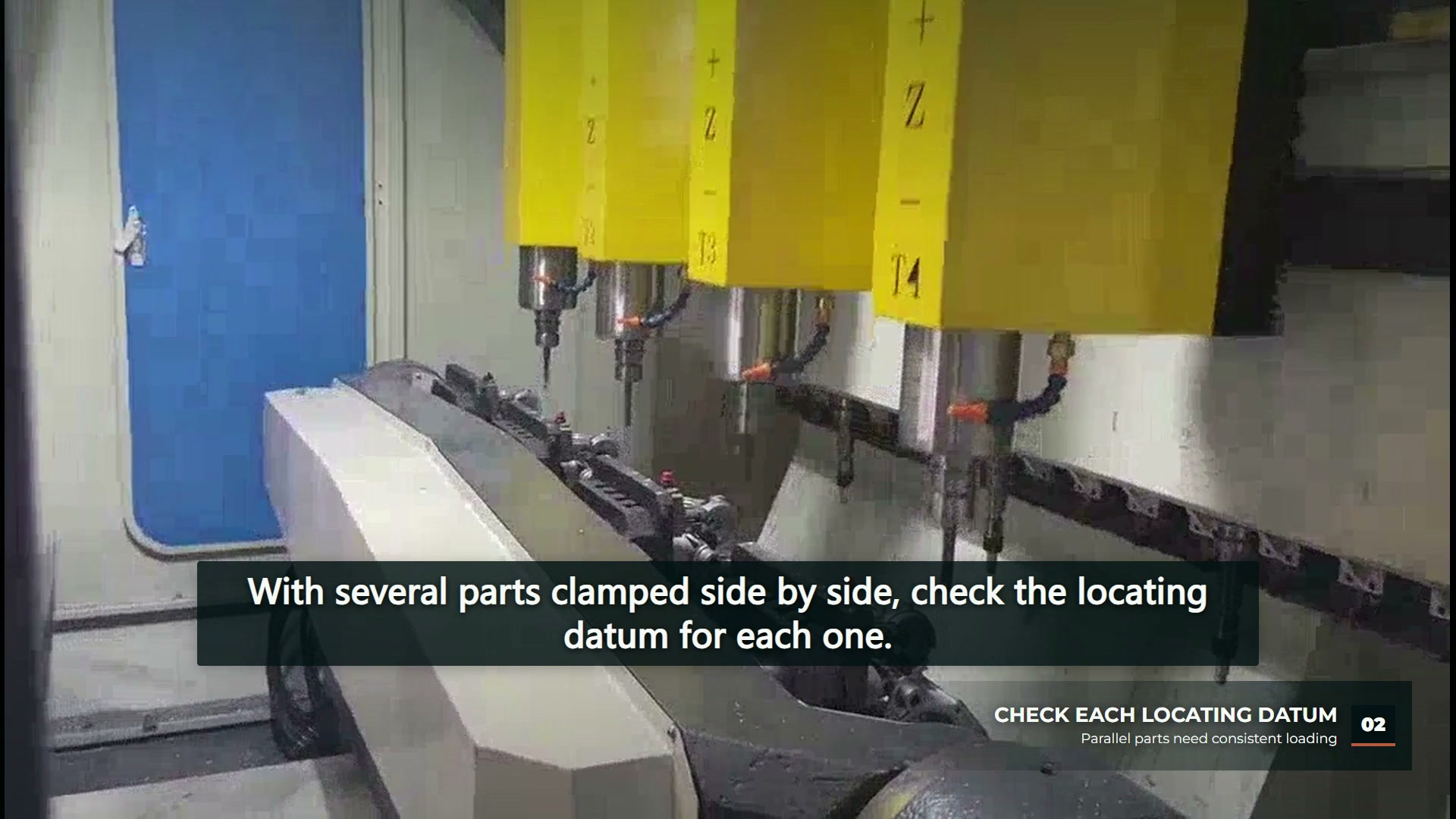
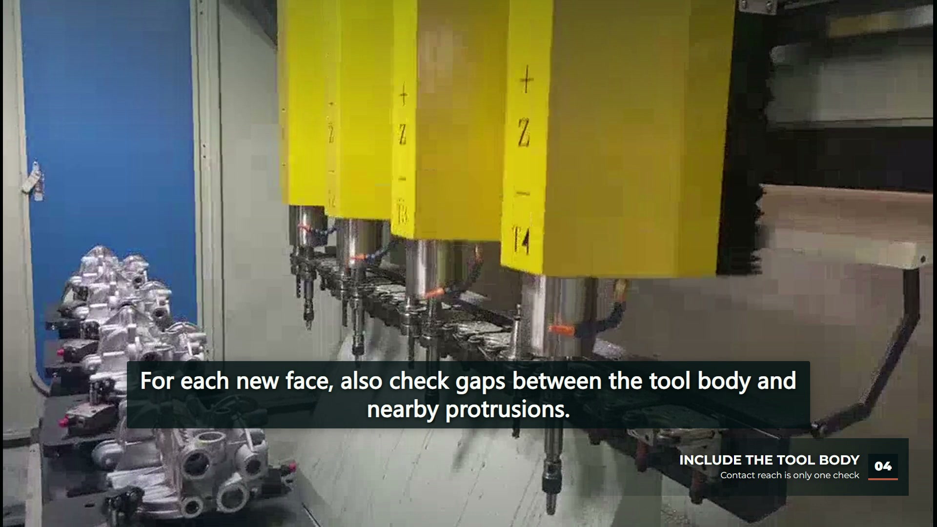
For a proposed installation, identify the intended datum contacts at each position before deciding that a shared movement is sufficient. Ask which incoming surfaces establish height and orientation, where variation is expected, and how an incorrectly seated casting would be recognized. An apparently repeated fixture can still need position-specific inspection evidence.
Carr Lane’s workholding principles explain the separate duties of locating a workpiece and retaining it against its locators. Applied to this review, the question is which contacts preserve the required relationship to the tool when another face is presented. The drawing and actual fixture establish that answer, not the number of heads visible in the video.
Review the intermediate angles
An end position can look open while an intermediate orientation creates the closest approach. Trace the most protruding part feature and the fixture hardware through the proposed rotation. Compare that swept region with the complete cutting assembly, including holders and adjacent heads. Tool-tip coordinates alone leave these other shapes unexamined.
At 00:23 the upper tools are clear of the visible workpiece region. This is a useful point for inspecting withdrawal, but a single frame cannot prove clearance throughout the motion. The engineering check needs the proposed rotation range, the retracted tool geometry and the permitted sequence. Record the pose that gives the smallest margin, rather than recording only the final machining pose.
There is a design tradeoff if extra withdrawal creates space but lengthens the movement between operations. It should be evaluated after the required clearance and operating conditions are established. The edited film supplies neither a complete cycle-time measurement nor the geometry needed to quantify that tradeoff.
Keep fixture acceptance and machining acceptance distinct
Build the acceptance record around the question being answered:
- Seating: Can each representative incoming part establish the required contacts at its assigned position? Record the part condition and fixture position together.
- Presentation: After the required turn, is the intended feature presented relative to the tooling as the process requires? Define the measurement against the part drawing.
- Passage: Does the full assembly have room through withdrawal, rotation and approach, including intermediate orientations?
- Machined result: Do the specified dimensions, material removal and surface requirements pass the agreed inspection?
The first three provide conditions for the process. They do not substitute for the fourth. A visible tool approach cannot tell a reader what allowance was removed or whether a finished surface meets its requirement. No such numbers can be recovered from these views.
Our article on fixture datum and flip recovery considers the related locating problem in a different application. Here the distinctive issue is the repeated tooling arrangement: compare each station’s datum condition and inspect the shared motion against the most restrictive part-and-fixture geometry. That produces a more useful review record than a single label saying that all four stations are reachable.