Define the panel envelope, allowed support regions, placed-stack state and release clearance before choosing a robot path. Discuss an application or email sales@evsrobot.com with panel drawings, presentation and stack requirements.
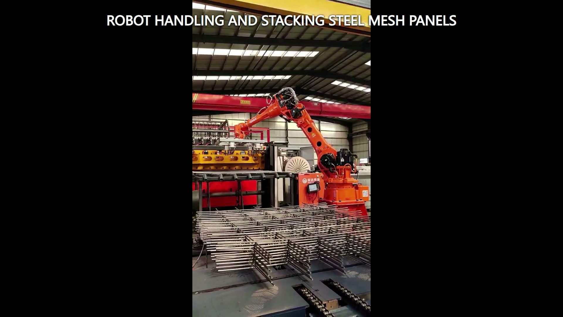
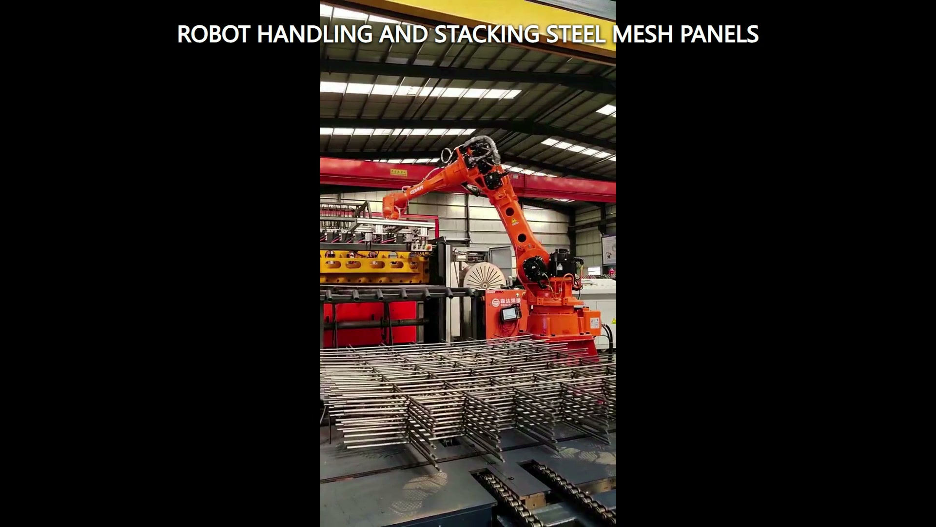
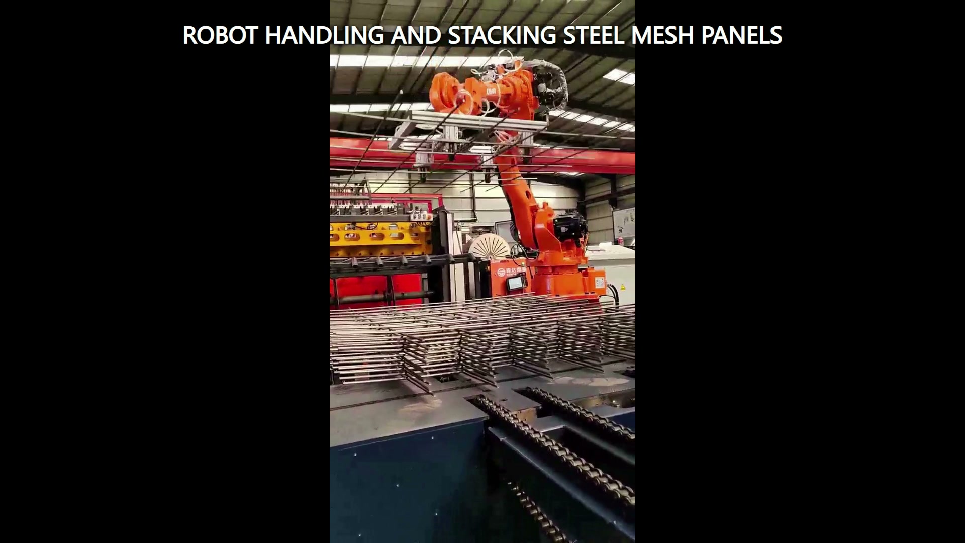
The footage shows an orange industrial robot with a rectangular end tool moving and stacking welded steel mesh panels at a transfer and stacking station. The projecting bars and layered panels make envelope control more important than a single nominal pickup coordinate.
Model the panel as a variable envelope
A mesh panel combines an outer rectangle, intersecting bars and many projecting edges. Record overall length and width, bar spacing, edge projection, flatness range and the conditions in which panels may overlap or interlock. The handling model should include the tool and panel together through the full motion.
Use boundary samples rather than one ideal drawing. A bowed panel can increase the swept volume; shifted bars can reduce tool clearance; two panels that partially catch can create an unexpected combined load. These states belong in feasibility trials and recovery planning.
Define support and contact restrictions
Mark where the panel may be supported or contacted and where the end tool must remain clear. The selected method must maintain a usable panel state through lift, transfer, placement and release. Tooling choice should follow actual drawings, samples, surface constraints and trials.
The footage establishes a rectangular end tool, but the project should specify its working principle independently. The application model needs the tool body, hoses or cables, panel deflection and nearby structure as one envelope.
Specify the placed stack as a state
A stack is not complete merely because a panel reaches a coordinate. Define edge alignment, permitted rotation, supported area, layer separation if applicable, maximum planned stack condition and the clearance required for tool release. State how the next panel is located relative to the stack datum.
The release path should leave without dragging projecting bars or disturbing the adjacent layer. Check the first layer, intermediate layers and the highest planned condition. Each can present a different tool angle and surrounding clearance.
Plan difficult-state recovery
The state table should cover source occupied, panel confirmed, destination available, placed state confirmed and tool clear. Add responses for a missing panel, shifted panel, suspected double panel, occupied destination or incomplete release. The project team should decide which conditions stop for inspection and which enter a controlled recovery.
Trials should record the incoming panel state, actual support condition, tool confirmation, placed orientation, edge alignment and recovery outcome. This provides better evidence than recording only whether the robot completed a motion.
Build the feasibility package
Provide drawings and boundary samples, mass and centre-of-gravity range, flatness and edge-projection limits, permitted support regions, source presentation, target stack drawing, stack datum, surrounding layout, required confirmations and acceptance method. Include the lowest and highest stack states and any panel variants sharing the station.
Robot, tool, panel, stack, transfer equipment and access conditions should be reviewed as one integrated application. Kontakta EVS to examine the envelope, support map, placed state and trial matrix. Email sales@evsrobot.com.
The footage supports only the visible orange robot, rectangular end tool, welded steel mesh panels and stacking motion; gripping principle, payload, cycle time, precision, stack quality and customer identity require project evidence.