
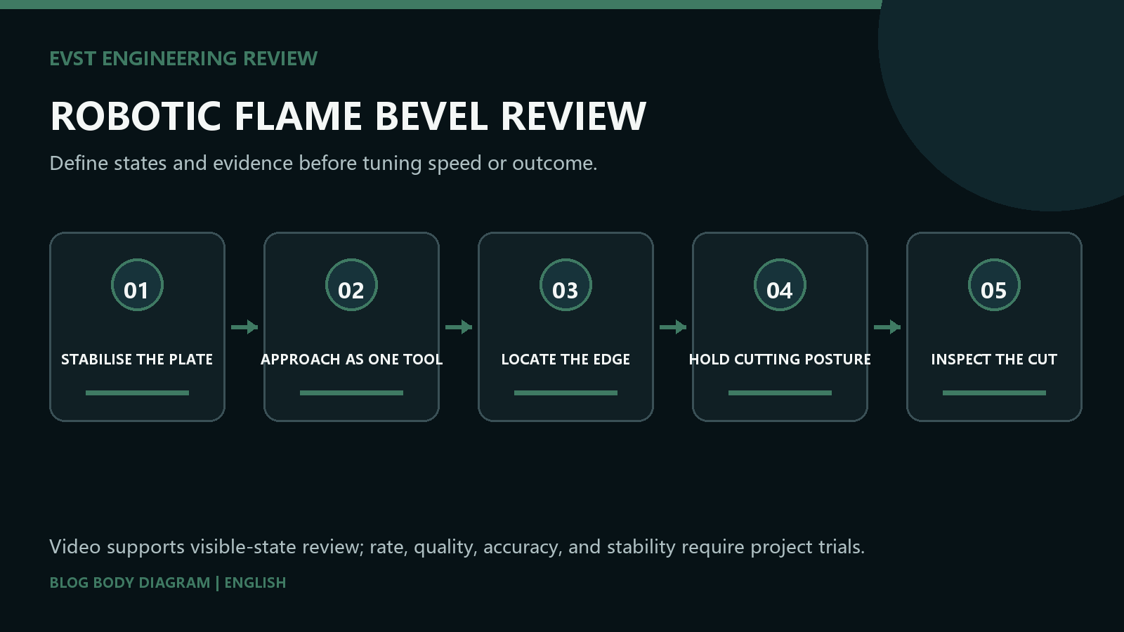
Direct answer: Robotic flame beveling should locate the actual plate edge before it executes the cut path. EVST separates four states: stabilize the plate datum, approach with the complete sensor-and-torch envelope, establish the path start from measured position, and hold the required tool posture along the edge. Offset, kerf and bevel quality remain inspection results.
Who this is for: Fabrication engineers and equipment buyers assessing seam finding before robotic flame bevel cutting on plate edges.
Scope: This EVST guide uses footage in which a robot approaches a plate edge, performs a locating action and follows the edge with a cutting tool. It explains datum, locating, posture and retreat boundaries; it does not prove sensing accuracy, kerf width, bevel angle, cut speed or edge quality.
Why robotic flame beveling starts with the real edge
A nominal drawing edge and the edge presented in a cell are not automatically the same reference. Plate placement, edge preparation and support conditions can move the path start relative to the robot frame. The locating step exists to establish that relationship before cutting begins, not to decorate an already fixed program.
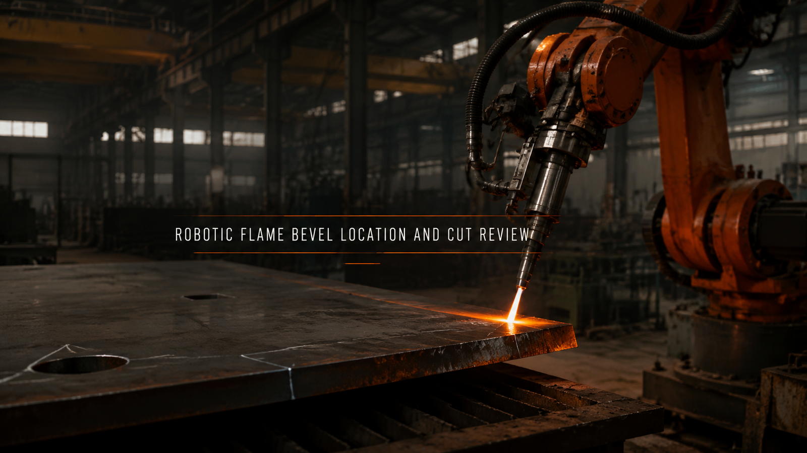
The reviewed footage shows a plate edge, a robot-mounted tool approaching from above, a locating action and a subsequent pass along the edge. It supports a sequence discussion. It does not reveal the sensor principle or prove how much correction was applied, so those details stay outside the claim boundary.
Robotic flame beveling is a controlled chain of evidence. The plate first rests on a declared datum; the complete sensing and cutting assembly approaches with clearance; the locating result establishes the actual path start; the cutting posture remains continuous along the edge; and the tool retreats before another edge is treated as a new condition. A visible pass proves only that this motion occurred. It does not establish sensing accuracy, kerf width, bevel angle, cut speed, heat-affected condition or downstream weld readiness. Those results require the actual plate specification, a recorded locating method, a repeatable cutting procedure and inspection of representative edges. Keeping the location result separate from cut acceptance prevents one successful movement from being mistaken for a qualified bevel process.
Plate support decides whether location can repeat
In practice, the plate needs a support and locating scheme that keeps the relevant edge stable during both measurement and cutting. A sensor can compensate for position variation only within its declared range; it cannot make an unsupported or moving edge into a reliable datum.
According to ISO 12100:2010, machinery limits are defined before risk reduction measures are selected. Here those limits include the plate envelope, support points, possible edge movement, access for loading and the space occupied by the robot, torch and services.
Treat the sensor and torch as one moving envelope
Endpoint reach is incomplete evidence. The locating device, flame torch, mounting bracket, wrist and service lines all need a clear approach and exit. A posture that lets the sensor see the edge may still put the cutting tool or cable pack close to a support.
According to ISO 10218-2:2025, the robot application and cell are assessed as a system. The interference review therefore uses the real tool geometry and every declared edge orientation rather than a point representing the robot flange.
Separate edge location from bevel execution
Location establishes where the edge is. Execution establishes how the torch travels relative to that edge. The program records the transformation between those two states and defines what happens when the locating result is absent, outside range or inconsistent with the expected plate condition.
The required bevel posture is a process input. At direction changes or a new edge, the robot must retain wrist margin and re-establish the location condition instead of copying an offset from the previous segment.
Choose the correction strategy from observed variation
A stable plate family with controlled presentation may need only a start-point correction. Variable edge position may require more sampling, while variation along the edge may call for tracking or tighter upstream preparation. The least complex method that covers measured variation is easier to verify and recover.
According to ISO 9283:1998, robot performance characteristics are measured under defined conditions. A robot characteristic alone is not a sensing-system accuracy claim, and neither value substitutes for verification on the real plate and tool stack.
| Observed condition | Location strategy | Evidence to request |
|---|---|---|
| Stable edge, shifted start | Start-point location | Repeated start measurements |
| Edge angle varies between parts | Two-point or feature location | Angular correction range |
| Edge varies along the cut | Tracking or tighter preparation | Path error and cut-edge inspection |
Inspect the cut edge, not the smoothness of the robot
A continuous robot movement is useful path evidence, but the bevel result is read on the cut edge. According to ISO 9013:2017, thermal-cut quality is described with defined geometrical and surface criteria; the applicable class and measurement method belong in the project specification.
Acceptance therefore links the plate and bevel definition, locating record, cutting condition and edge inspection. If the material, support, edge condition or torch changes, the affected location and cutting evidence is reviewed again.
Frequently asked questions
Why locate the edge before flame beveling?
Because the programmed path needs a measured relationship to the plate actually presented in the cell.
Does edge finding prove the bevel angle?
No. It establishes position; bevel geometry still depends on tool posture, process condition and inspection.
Can one correction be reused on another edge?
Only after that edge is shown to share the same datum and variation; otherwise it is a new location case.
What should acceptance measure?
Use the specified cut-edge criteria, locating records and representative parts rather than the appearance of robot motion.
Project inputs for an application review
A robotic flame bevel review starts with the plate datum, observed edge variation and the cut-edge requirement.
- Plate size, material and support method
- Edge positions, bevel form and protected zones
- Locating method and expected variation range
- Torch geometry, services and approach directions
- Cut-edge criteria and inspection method
Send those project inputs to EVST for a bounded review of locating, tool access, cutting posture and acceptance evidence. Related reading: cutting automation acceptance, welding and cutting path boundaries, large workpiece pose and reach test.