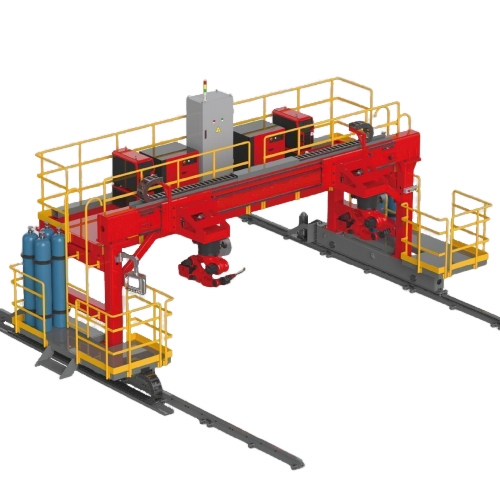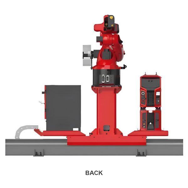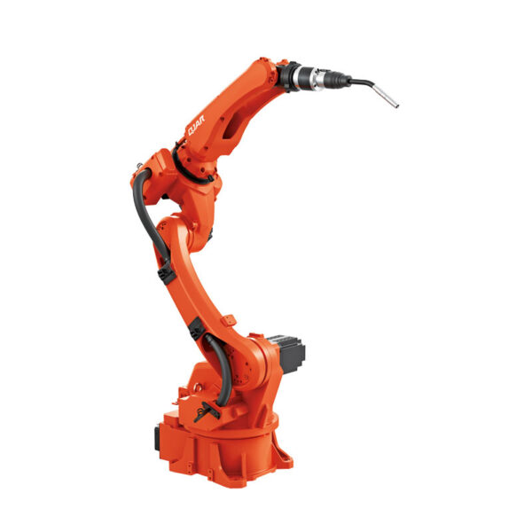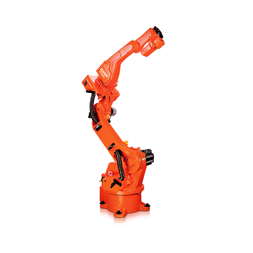
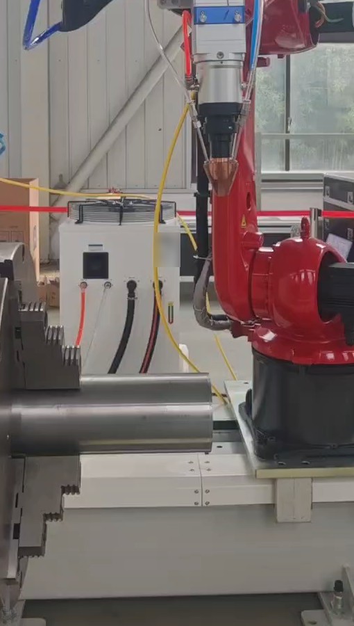
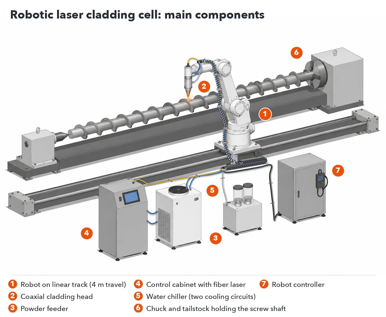
A robotic laser cladding system combines six main parts: a six-axis industrial robot, a cladding head with coaxial powder feeding, a powder feeder, a continuous fiber laser, a water chiller, and a way to present the part, usually a chuck for rotating parts and a linear track for the robot. The robot, laser and chiller are standard industrial components; the cladding head, the powder feeder and the integrated control cabinet are built specifically for cladding.
| Komponentas | Ką ji daro | Standard or built for cladding |
|---|---|---|
| Šešių ašių pramoninis robotas | Moves the cladding head along the programmed path | Standard industrial robot |
| Linear track | Extends the robot’s reach along long parts; 4 m effective travel in the standard cell | Built to the cell layout |
| Chuck / rotary axis | Holds and rotates shafts, rods and tubes for OD cladding | Sized to the part |
| Apdailos galvutė | Focuses the laser and delivers powder coaxially into the melt pool | Built for cladding |
| Miltelių tiektuvas | Meters powder to the head at a steady rate | Built for cladding |
| Skaidulinis lazerio šaltinis | Supplies the continuous laser beam (1080 nm) | Standard laser source, housed in the control cabinet |
| Vandens šaldytuvas | Cools both the laser source and the cladding head | Standard chiller, sized to the laser power |
| Kontroles kabinetas | Integrates the laser, monitoring and the HMI; carries the IoT module for remote diagnosis | Built for cladding |
Laser safety guarding around the cell is planned for each installation.
Choose the configuration by the surface you need to clad. OD cladding covers the outside of shafts, rods, tubes and pipe ends: a chuck rotates the part while the robot moves the head along it, laying a continuous spiral bead. Flat-surface cladding covers plates and flat faces: the robot lays parallel beads side by side, each one overlapping the last, until the area is covered. One cell can be set up for both, as long as the chuck and the flat work area are planned into the layout.
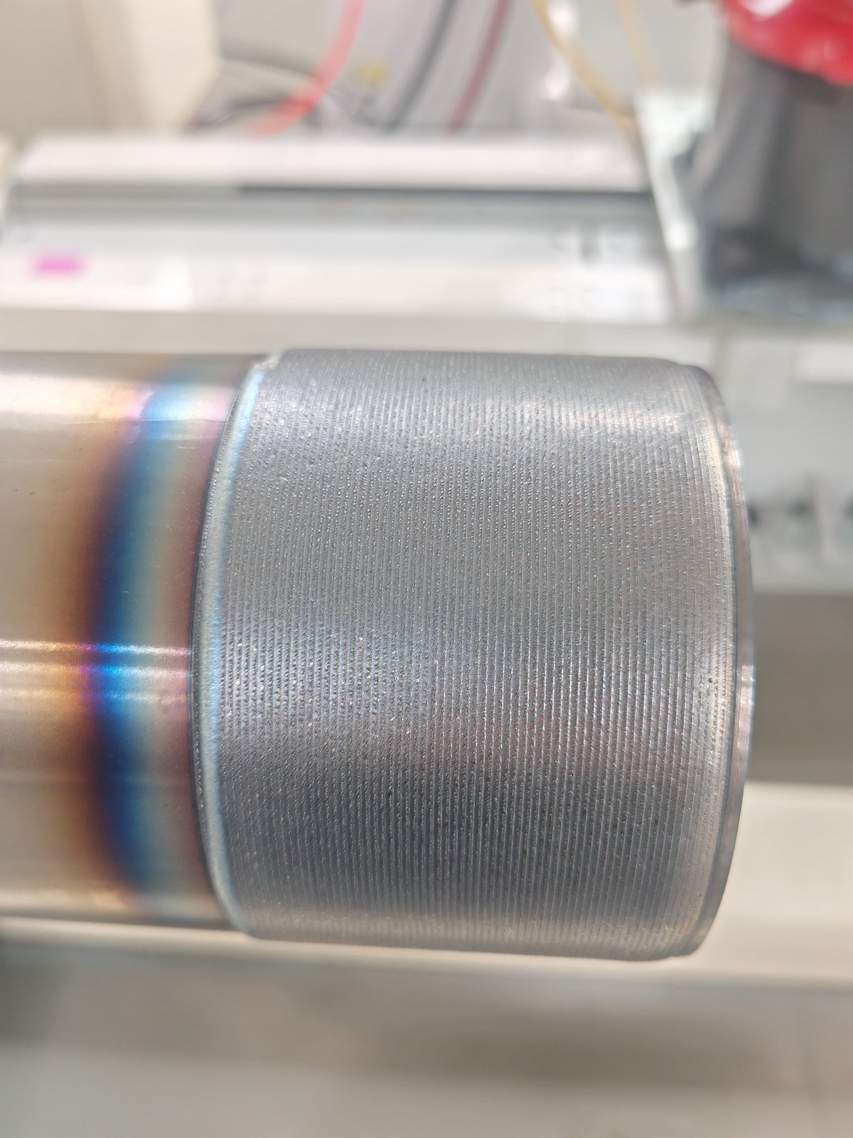
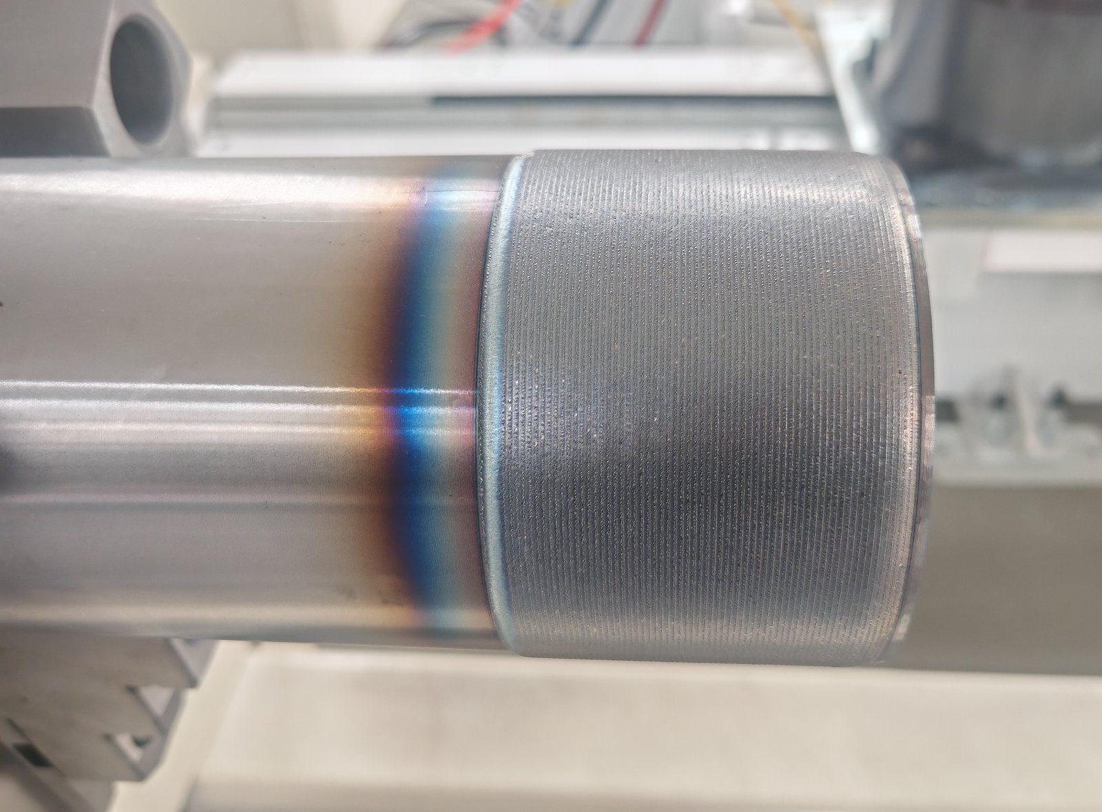
The part is clamped in a chuck and rotated; the robot holds the cladding head over the surface and traverses along the axis. The clad band in the trial below is even along its length, and the tinted band beside it is the heat-affected zone on the base metal.
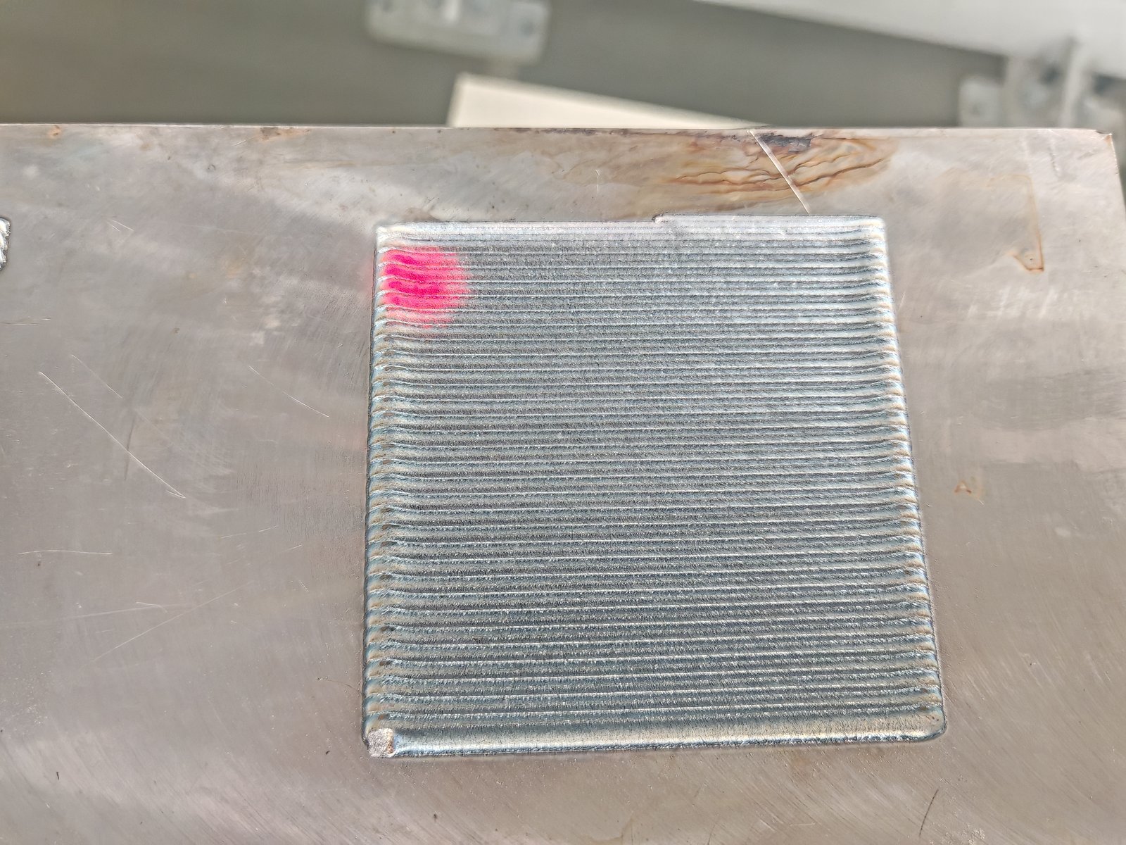
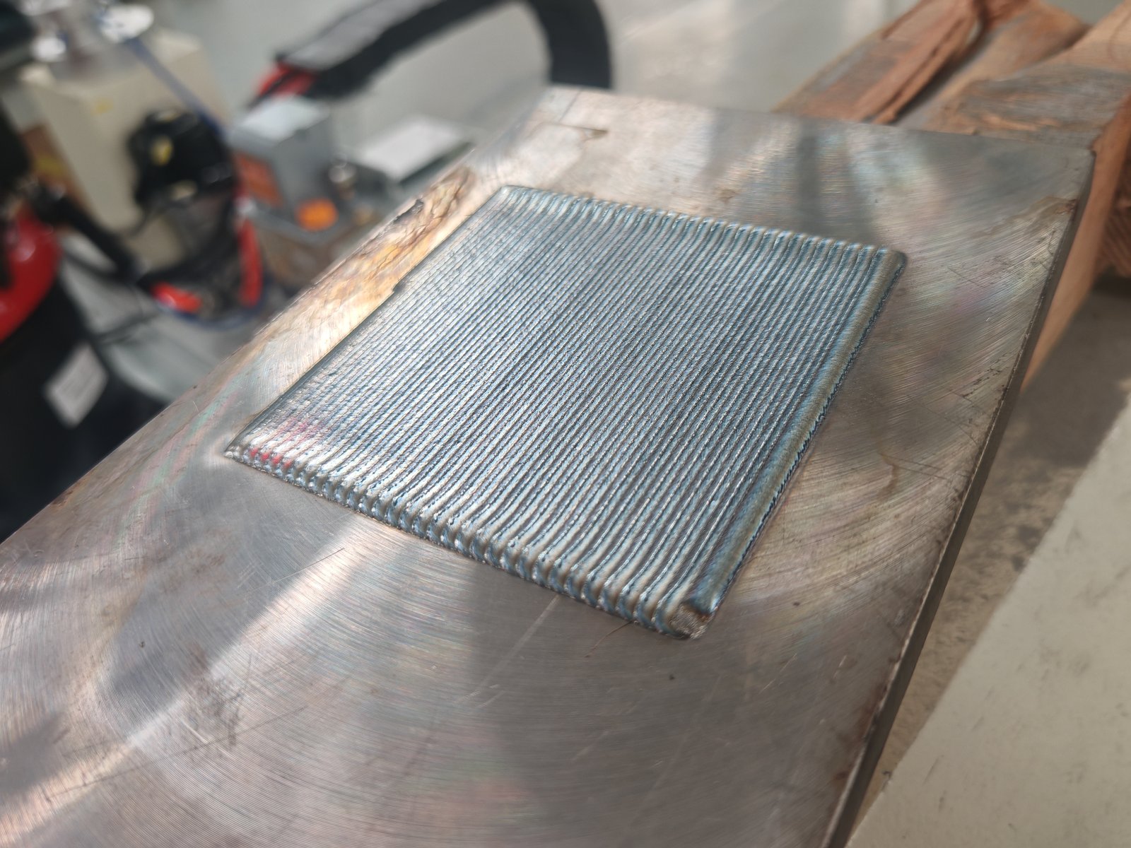
The robot lays bead after bead with a set overlap, building a uniform layer across the area. The square trial patch below shows the multi-pass pattern.
For how the laser cladding process works and what it is used for, see our laser cladding process basics and demo.
Internal bores need a dedicated internal cladding head that fits inside the bore. Bore work is usually done on a dedicated CNC cladding machine; see the next section.
Choose a robotic cell when your parts vary in shape and size, when you need both OD and flat-surface work, or when the cell must fit around an existing layout. Choose a dedicated CNC laser cladding machine when most of your work is one part family, such as hydraulic cylinder rods or bores in steady volumes, and you want enclosed machine-tool rigidity and fixed setups.
| Robotic laser cladding cell | Dedicated CNC laser cladding machine | |
|---|---|---|
| Geriausiai tinkantis | Mixed parts: shafts, rods, tube ends, plates, flat faces; repair and small batches | One part family in volume: cylinder rods, columns, bores |
| Paviršiai | OD and flat surfaces in one cell; free-form paths are programmed on the robot | OD, or ID with an internal head, or a combined OD/ID machine |
| Judėjimas | Robot path plus chuck rotation and linear track | X/Y/Z axes plus a rotating spindle; 0.01 mm / 0.01° resolution and repeatability |
| Dalies dydis | Set by the chuck, track travel and robot reach for each project | OD machine: up to Ø630 mm × 3,000 mm, 2 t. ID machine: bores Ø180 mm (Ø100 mm optional) to Ø500 mm, up to 2,500 mm long, 2 t. Combined OD/ID machine: OD up to Ø1,000 mm, length 5,000 mm or more |
| maketavimas | Fixed station, open layout arranged to fit the plant | Enclosed machine with its own footprint |
When a dedicated machine fits better
If your work falls into one of these cases, tell us the part family when you ask for a quote and EVST will review a dedicated machine configuration alongside the robotic cell.
Powder, not wire. The system feeds powder coaxially: the nozzle surrounds the beam, so the powder reaches the melt pool evenly from every direction. That is what lets the robot change direction freely along a path. The standard configuration is powder-fed; wire feeding is not part of it.
High-speed head or wide-band head for OD work. Both are offered for OD cladding. Reference figures from the dedicated OD machine configuration, for a 1.2 mm clad layer:
| Galvos tipas | Cladding time per m² (1.2 mm layer) | Powder utilization |
|---|---|---|
| High-speed cladding head | 2–2.5 h/m² | 85 – 90% |
| Wide-band cladding head | 1.5–3 h/m² | 95% arba daugiau |
| Through-bore head (ID) | 3 h/m² | 85 – 90% |
| Blind-bore head (ID) | 3.5 h/m² | 85 – 90% |
The wide-band head wastes less powder; the high-speed head works in a narrower time range. Because powder is the main running cost (see below), powder utilization matters as much as speed when you compare heads.
Powder feeder. Powder feeders on the cells we have delivered are pneumatic (carrier-gas) or gravity units, servo-driven, running from 5 to 100 g/min, continuously adjustable, with ±3% feed stability.
Laser power. Systems we have built use continuous fiber lasers from 6 kW to 12 kW, at 1080 nm, with power adjustable from 10% to 100%. Higher power raises the deposition rate and the area covered per hour. The final laser power and feeder setup are selected for each project based on your parts, coating requirement and output target, and confirmed in the cladding trial.
The first question EVST asks is whether the surface fails by wear or by corrosion. That choice decides the cladding powder, and the process parameters follow from it. A rod that wears against seals and a part that corrodes in seawater need different powders and different settings, even on the same machine. Tell us how the part fails in service, not only its drawing.
Laser cladding runs at high power for long periods, and much of that energy ends up as heat. The chiller therefore runs two cooling duties: one for the laser source and one for the cladding head at the robot wrist. Temperature control is critical to stable output, and the chiller is sized to the laser power; smaller chiller sizes are available where the laser power allows.
Fiber laser cooling water is typically held around 22 °C. If the air around the laser is warm and humid enough that its dew point rises above the water temperature, moisture condenses inside the laser. In humid climates, plan a cabinet air conditioner or dehumidification for the laser enclosure.
Dust on a lens or protective window absorbs laser energy and can burn the optics, damaging the cladding head or the laser output. This is why laser cladding equipment is harder to build than conventional welding equipment: the optical path is assembled in a dust-free room and kept sealed from powder and dust.
The equipment is a one-time purchase; powder is consumed every shift. Two machines can use tens of kilograms of powder in two days, and regular users buy it by the tonne. Over the life of the cell, powder becomes one of the largest cost items. When you compare systems, compare powder utilization and the powder supply, not only the machine price. EVST supplies cladding powder matched to the application.
Laser cladding equipment is less forgiving than welding equipment: wrong operation can damage the laser source or the cladding head. Knowing the process matters more than the hardware, which is why EVST includes on-site training rather than relying on remote instruction alone (see below).
The working range of a robotic laser cladding cell is set by four things: the chuck or rotary axis that holds the part, the linear track that carries the robot along it, the robot’s reach, and the floor area for flat parts. EVST sizes each of them to your largest part, so most limits below are configured per project rather than fixed.
| Working-range item | Robotic laser cladding cell |
|---|---|
| Maximum part diameter (OD cladding) | Configured per project: set by the chuck and the robot’s reach |
| Maximum clad length | Configured per project: the robot travels along the part on the linear track |
| Linear track travel | 4 m effective travel (standard cell) |
| Maksimalus dalies svoris | Configured per project: set by the chuck and rotary axis rating |
| Pupytė | Three-jaw chuck on a rotary axis for shafts, rods and tubes; size configured per project |
| Rotary axis / positioner payload | Konfigūruojama pagal projektą |
| Plokščios dalys | Configured per project: set by the robot’s reach, the track travel and the work area in the layout |
| Reference: dedicated OD cladding machine | Up to Ø630 mm × 3,000 mm clad length, 2 t |
To size the cell, send the largest diameter, the length to be clad, the weight and center of gravity of the heaviest part, and the size of any flat parts.
| Punktas | Specification (configurations built to date) |
|---|---|
| Ląstelės tipas | Fixed-station robotic laser cladding cell, without a mobile platform; arranged to fit the plant layout |
| Konfigūracijos | OD cladding (chuck rotation); flat-surface multi-pass cladding |
| Robotas | Six-axis industrial robot; payload and reach selected for the cladding head and the part |
| Linear track | 4 m effective travel (standard cell) |
| Lazerio šaltinis | Continuous fiber laser, 1080 nm; 6–12 kW on systems built to date; power adjustable 10–100%; QBH fiber output; water-cooled; 380 V input; remote and local control |
| Apdailos galvutė | Coaxial powder-feeding head; high-speed or wide-band head for OD work |
| Miltelių tiektuvas | Pneumatic (carrier-gas) or gravity; servo drive; 5–100 g/min continuously adjustable on delivered cells; feed stability ±3% |
| Aušinimas | Water chiller sized to the laser power; cools the laser source and the cladding head |
| Kontrolė | Integrated control cabinet with laser source and monitoring; touchscreen HMI |
| Nuotolinė diagnostika | IoT module for remote viewing of the HMI and operating data; can be disconnected when not needed |
| Lazeriniai signalai | Read over an Ethernet cable with PC software (English version available) |
Specifications on this page are typical values from configurations built to date; laser power and powder feeder setup for your cell are chosen per project. Cladding rate, layer thickness, layer quality and powder utilization depend on the part, base material, powder and coating requirement, and are confirmed for each project in a cladding trial.
Factory acceptance, installation and on-site commissioning are agreed for each project and set out in the quotation.
EVST recommends 1–2 days of on-site training at delivery. It covers operating the control system, setting parameters for wear-resistant and corrosion-resistant work, and the routine checks that protect the optics. Remote instruction is not a substitute for hands-on training on your own parts.
The IoT module lets EVST engineers see the touchscreen and the operating data remotely, which helps locate faults quickly even across a language barrier. The module ships with a Chinese SIM card that has no international roaming; replace it with a local SIM card when the system arrives, or connect the module to your network.
If you do not want production data to leave the plant, run the system with the SIM card removed or the IoT module’s network cable unplugged. Connect it only when a fault needs remote diagnosis, and disconnect it again afterwards.
When the laser source raises an alarm, the code is read by connecting a PC to the laser over an Ethernet cable and opening the laser’s diagnostic software, which has an English version. EVST covers this step in training so that your team can retrieve fault codes without waiting for support.
Warranty terms are confirmed in the quotation. For overseas plants, EVST ships spare parts for local replacement and guides the work remotely; this is faster than waiting for an engineer to travel across time zones. On-site visits abroad can be arranged, with travel and service costs agreed in the contract beforehand.
Lead time depends on the configuration and is confirmed in the quotation; shipping time depends on the destination.
A quote for a robotic laser cladding system starts from five inputs. With them, EVST can arrange sample cladding trials on your parts before an order.
A robotic laser cladding system is a cell in which an industrial robot moves a laser cladding head over a part, melting metal powder into its surface to build a dense, metallurgically bonded wear- or corrosion-resistant layer. The EVST system pairs a six-axis robot on a linear track with a coaxial powder head, a continuous fiber laser, a powder feeder and a water chiller, plus a chuck for rotating parts.
A robotic laser cladding cell includes the robot, the fiber laser, the cladding head, the powder feeder, the water chiller, and a chuck or linear track to present the part. In the EVST cell, the robot, laser and chiller are standard industrial components; the cladding head, powder feeder, integrated control cabinet and cell base are built specifically for cladding; and the chuck, track and layout are sized to your parts. EVST integrates them into one cell and sets the robot paths, process parameters and powder for your parts.
For mixed shafts, rods, tube ends and flat parts, a robotic cell is more flexible: one cell handles OD and flat surfaces and fits an open layout. For one part family in steady volume, such as cylinder rods, or for cylinder bores, a dedicated CNC machine is the better fit.
One robotic cell can handle OD and flat-surface cladding when the chuck and the flat work area are both planned into the layout. Internal bores need an internal cladding head and are normally clad on a dedicated machine; a through-bore head leaves about 30 mm at the cylinder bottom unclad unless the bottom is cut off, while a blind-bore head clads the full depth.
The EVST system uses coaxial powder feeding. The nozzle delivers powder around the beam from every direction, so the robot can change direction along a path without changing how the powder enters the melt pool. Powder also gives a wide choice of wear- and corrosion-resistant alloys. Wire feeding is not part of the standard configuration.
Systems EVST has built use continuous fiber lasers from 6 kW to 12 kW. Higher power covers more area per hour, but the power for your cell is assessed per project from the part diameter and length, the layer thickness and your output target, and confirmed in a cladding trial on your parts.
For a 1.2 mm layer in OD work, a high-speed head runs at about 2–2.5 h/m² with 85–90% powder utilization, and a wide-band head at about 1.5–3 h/m² with 95% or more. The wide-band head wastes less powder, which matters because powder is the main running cost.
Specify the largest diameter, the length to be clad, the weight and center of gravity of the heaviest part, and the size of any flat parts. EVST sizes the chuck, the rotary axis, the linear track and the robot reach to those parts; the standard cell’s linear track has 4 m of effective travel, and the other limits are configured per project. For reference, a dedicated OD cladding machine takes parts up to Ø630 mm × 3,000 mm and 2 t.
Yes. Hydraulic support columns, jacks and cylinders for coal-mining equipment are a main application of laser cladding, both for new parts and for remanufacturing worn ones. Rods and columns are clad on the OD; cylinder bores are clad with an internal head.
Laser cladding is used on components for mining equipment, power generation, metallurgy, petrochemicals and offshore engineering, including oil well pipe, shafts and large equipment parts that are repaired or remanufactured. Production lines for cladding oil well pipe can be designed to order.
Ask four things before buying: will the supplier clad sample parts to your coating requirement before the order; can it supply cladding powder matched to your service condition; will it train your operators on site; and how will it support you after delivery, including remote diagnosis and spare parts. EVST supplies the equipment, matched powder and process setup together for this reason.
Plan 1–2 days of on-site training at delivery, covering the control system, parameter setting for wear and corrosion work, and optics care. After that, the IoT module lets EVST engineers diagnose faults remotely; overseas, fit a local SIM card because the shipped SIM has no international roaming.
Yes. EVST ships spare parts for local replacement, guides the work remotely, and diagnoses faults through the system’s IoT module once a local SIM card is fitted. For data security, the SIM card or the module’s network cable can stay disconnected in normal production and be connected only when a fault needs remote support.
Warranty terms and lead time depend on the configuration and are confirmed in the quotation. After delivery, overseas plants are supported through shipped spare parts and remote guidance; on-site visits abroad are arranged with travel and service costs agreed in advance.
The price of a laser cladding system depends on the laser power, the cladding head types, the chuck size and linear track length, whether the cell does OD only or OD plus flat-surface work, the chiller size, and on-site commissioning and training. Running cost is mostly powder, so ask for the expected powder utilization as well. EVST quotes per project after reviewing your parts; susisiekite su mumis with drawings and the coating requirement.
All figures on this page are typical values; actual cladding performance is confirmed for each project in a cladding trial.