
By Redazione EVST · Recensito da Redazione EVST · Ultimo aggiornamento: 12 ottobre 2026 · Politica editoriale · Politica di correzione · Termini e condizioni
In this grinding cell, a rotary fixture with yellow A, B and C dividers presents cylindrical jack components to a stationary robot. Each index brings the next clamped position into the robot’s working range. The tool approaches the workpiece, makes contact, retreats, then reaches a lower position toward the front before the next fixture index.
Evaluating a similar part? Send us the drawing, fixture concept, surfaces to be processed and daily output, and we will help map access, indexing and trials.
Read the cell in the right order
The yellow dividers make the index positions easy to see. The rotary fixture changes orientation and brings each clamped part position to the robot in sequence. The visible sequence is:
- The fixture indexes to a new orientation.
- The robot approaches a cylindrical workpiece at the rear position and makes contact.
- The tool withdraws from that position.
- The robot moves to a lower position toward the front, makes another contact and retreats.
- The fixture indexes again for a similar cycle.
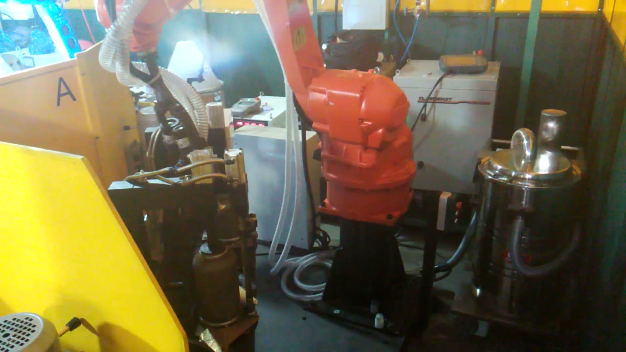
The bright spot visible near the work area is a work light, not a welding arc. The sequence is a grinding operation with two distinct robot approaches around the indexed fixture.
Indexing defines when the robot may enter
A rotary fixture improves access by presenting several positions around one axis, but it creates a shared-motion zone. The robot should only enter after the fixture has reached its commanded position and the clamp state is confirmed. The fixture should only index after the robot and tool have cleared the swept volume.
This handshake is more than a program delay. A robust concept defines positive conditions for fixture-in-position, clamp-ready and robot-clear. It also defines what happens after a stop: the system needs to know which index is present and whether the tool is safely outside the fixture envelope before either axis resumes.
Two contact regions need two clearance studies
The rear and front-lower contacts use different approach directions. A route that is clear behind the divider may bring the wrist, hose or tool body close to the fixture when the robot descends toward the front. Treat them as separate access studies even if they belong to one process recipe.
| Contact region | Visible motion | Controllo tecnico |
|---|---|---|
| Posizione posteriore | Approach, contact and withdrawal behind the divider | Divider clearance, wrist posture and retreat path |
| Front lower position | Lower approach, contact and withdrawal nearer the front | Tool-body and hose clearance, joint margin and fixture edge |
| Index move | Yellow divider and fixture rotate | Robot-clear zone, position confirmation and restart logic |
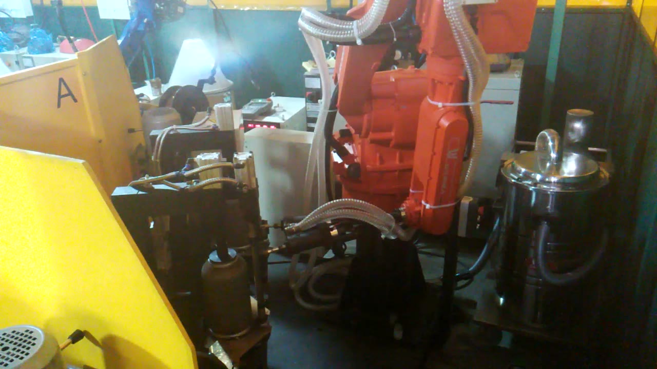
The corrugated hose also belongs in the envelope check. Its routing changes as the wrist turns, so a clear tool tip does not by itself prove that the complete assembly is clear.
Fixture location comes before path refinement
Grinding forces act through the part into the clamp and fixture. The cell concept should locate the workpiece consistently, resist movement during contact and leave the required region accessible. The divider may protect or separate positions, but its height and edge location also constrain the robot approach.
Begin trials with representative parts and the intended fixture. Verify the index repeatability at the process position, then teach the rear and front-lower routes. Run them slowly while watching the tool body, wrist, hose, clamp and divider. Only after motion and contact are stable should the process team set application-specific parameters and acceptance checks.
When this arrangement fits
This layout is useful when several clamped positions can be presented by one rotary fixture and each part needs repeatable robot access from more than one direction. It needs more development when part variation changes the contact location, the divider blocks the required approach, the hose cannot be routed through all wrist postures, or debris management and inspection need additional equipment.
Cosa inviare per una valutazione
- Part drawings and the surfaces or regions that require grinding.
- The proposed clamp and rotary-fixture geometry.
- Required index positions and the loading method.
- Tool and process supplier information.
- Acceptance criteria, output target and available cell space.
- Requirements for debris collection, guarding and inspection.
Contatta EVST or email sales@evsrobot.com with these inputs for an initial cell and trial plan.
This article describes the visible sequence and design checks for this cell type. Tool selection, contact surface, process settings, finish and production performance require confirmation with the actual part and equipment.