
Review a circumferential welding setup by locating the seam relative to both end supports, then checking the space required by the torch and by loading or unloading. These are separate equipment positions to assess. A fixture that holds the cylinder in a convenient welding position may still leave an unresolved route for introducing or removing it.
Locate the seam within the held assembly
At 00:03, the video shows a horizontal cylinder held between two end structures on a fixed welding machine. At 00:09, the closer view brings the seam area, torch and adjacent holding structure into the same picture. No articulated robot arm is shown in this selected sequence.
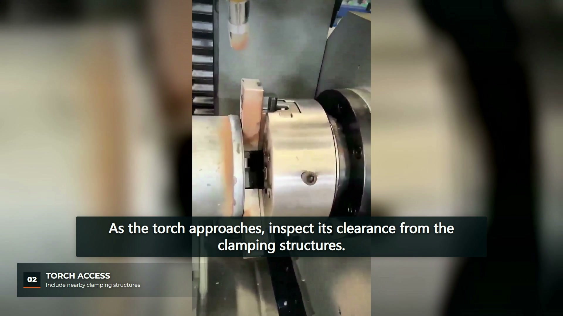
For an application review, draw the joint in its assembled and held condition. Include any support or clamp that occupies the approach space. Where cylinder length or end geometry changes, compare the new seam position with the same physical references. Do not assume that a change in part length affects only the distance between the supports.
Check the equipment’s working and loading positions
The public circumferential welding lathe description describes tailstock alignment adjustments and a welding head that swings rearward for loading access. These are features of that example machine. They explain why working access and loading access deserve separate questions; they do not identify the mechanism in the video.
For the proposed setup, identify which equipment moves clear during loading, what supports the assembly before final clamping and which structures remain beside the seam during welding. Use the machine’s actual operating and safeguarding requirements for that review. A photograph of an open work area cannot establish that a loading task is safe or that the required sequence has been validated.
Confirm the process before specifying the torch arrangement
The circumferential welder product description lists several available welding processes. Circumferential describes the seam arrangement; it does not uniquely identify a welding process. The application must establish its actual process and joint requirements before tool access can be accepted for that configuration.
The footage does not supply those procedure details, a dimensional inspection of the setup or a weld-quality result. A visible arc therefore remains an observation of operation, not evidence that the completed joint meets its requirements.
Carry the access decision into the trial
Keep a record of the cylinder and joint drawings, held seam location, support arrangement and intended loading route. When a representative assembly is tried, relate the observed access to that recorded configuration. A change in a clamp, support or torch arrangement should be traceable to the trial it affects.
The broader guide to joint stability in automatic circumferential welding discusses the wider welding and inspection record. This equipment review supplies a narrower input: whether the proposed held assembly leaves the required working and handling space. Acceptance of the weld remains a separate decision under the project’s inspection requirements.