
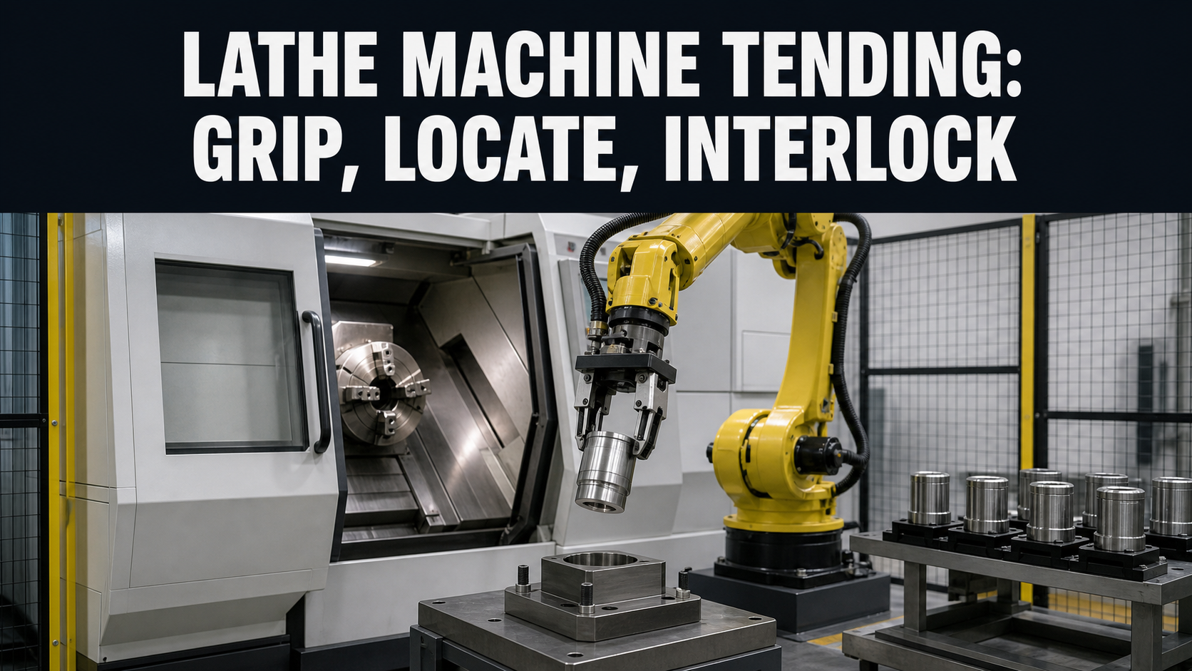
A robotic lathe tending interlocks design is complete only when the controls can explain whether the current object is a blank or finished part, who owns it, what the chuck has confirmed, whether machine access is permitted, and which state permits recovery. A successful demonstration of arm motion does not answer those questions by itself.
Key takeaways
- Keep blank, in-process, finished, rejected, and unknown part states distinct from physical tray position.
- Use separate evidence for door or access state, spindle or machine state, chuck command, chuck feedback, part seating, and robot clearance.
- Design gripper custody and exchange logic so a retained or dropped part cannot be misclassified.
- Include chip, coolant, jaw, and exit-path conditions in the physical clearance review.
- Validate controlled stops and restart states before using one best cycle as a capacity claim.
What the selected footage supports—and what it does not
The reviewed material shows cylindrical workpieces arranged on a tray, an industrial robot picking or placing parts, and robot interaction with a lathe work area and visible chuck region. The sequence supports a bounded discussion of blank presentation, robot pickup, machine approach, chuck access, removal, and return to a tray or outfeed position.
The footage does not expose the machine program, door circuit, chuck command or feedback, gripping confirmation, seating evidence, spindle state, jaw force, part dimensions, workholding analysis, cutting conditions, chip-clearing method, gauging, accepted cycle time, process capability, quality result, fault records, or site acceptance. EVST therefore treats the sequence as observable process context, not as proof of performance, safeguarding, compliance, or production deployment.
The visible parts appear cylindrical, but the article does not infer their material, tolerance, machining stage, final use, or customer. Those facts must come from controlled project inputs.
How to define robotic lathe tending interlocks
Start with the part-state map. Define raw blank, loaded but not machined, machining complete, removed but not inspected, accepted finished part, rejected part, and unknown state. Tie each state to evidence and a permitted destination. A tray pocket alone should not determine whether a part is raw or complete unless the tray design, loading procedure, and control record make that identity unambiguous.
Then define the physical datum chain. Record how the infeed presents the blank, which features the gripper contacts, how orientation is prevented or detected, which chuck or jaw surfaces locate the part, how insertion depth is established, and how the finished part is removed without damaging a controlled surface. If raw and finished geometry differ, verify that the gripper and nests accommodate both states without confusing them.
Finally, write each state transition as a handshake. The robot should request access; the machine should confirm the applicable loading condition; the robot should enter only after defined permissions exist; the part should transfer only when custody evidence is clear; and machining should remain unavailable until full robot clearance and required workholding evidence are valid.
Separate commands, feedback, and part evidence
A door-open command is not the same as an access-open indication. A chuck-close command is not the same as the specified clamped state. A gripper-close command is not proof that the expected part is present. Keeping those concepts separate lets the controls distinguish a late transition, a missing signal, a mechanical obstruction, and an incorrect part state.
For every interface point, document the request, acknowledgment, physical evidence, expected transition, diagnostic timeout, fail state, and recovery owner. If one signal is used for more than one decision, record the reason and the validation boundary. Avoid giving a convenient production status a safety meaning that its architecture and validation do not support.
Part seating deserves its own review. A chuck can move while the part is not at the intended stop, chips are trapped at the datum, or the part is cocked. The accepted evidence may involve controlled insertion, jaw position, pressure or force monitoring, part-presence sensing, or another project-specific method. This article does not prescribe one universal solution.
Lathe load-and-unload handshake table
| State | Evidence to define | Permitted action | If evidence is missing or contradictory |
|---|---|---|---|
| Blank ready | Correct part identity, orientation, pickup datum, pocket state, and gripper compatibility | Robot may request pickup and assign custody after confirmed grip | Hold the cycle and preserve the pocket and part state as unknown or blocked |
| Machine available for tending | Machining complete or loading mode active, spindle and conflicting machine motion in the required state, access condition confirmed | Robot may request and receive machine-zone ownership | Deny entry and diagnose the missing permission instead of relying on elapsed time |
| Finished part gripped | Gripper command, expected grip evidence, chuck-release condition, and part custody transfer | Remove the finished part along the validated exit path | Retain a restrictive state; do not assume either gripper or chuck owns the part |
| Blank inserted | Correct orientation, required seating depth or datum, gripper position, and chuck-ready condition | Command the specified workholding transition | Withdraw only through a defined recovery route or hold for authorized intervention |
| Chuck state confirmed | Specified workholding feedback and any required part-presence or seating evidence | Transfer custody from gripper to chuck and release the part | Keep machining unavailable and retain diagnostic evidence |
| Robot clear | Arm, gripper, cables, finished part, and any dual-gripper load outside the defined machine boundary | Release machine-zone ownership and permit the next validated machine state | Keep conflicting action unavailable and enter controlled recovery |
| Finished part routed | Part identity, inspection status, destination, pocket availability, and release confirmation | Store the completed or pending-inspection state | Prevent a disputed part from entering the accepted finished-part flow |
Choose a part-exchange architecture deliberately
A single gripper can simplify tooling and custody logic, but it may require the robot to place the finished part before acquiring the next blank. A dual gripper can exchange finished and raw parts during one machine visit, but it increases tooling mass, envelope, cable or hose routing, and the number of custody states. An intermediate exchange nest can decouple pickup and machine service, but it adds another datum, occupancy state, and recovery location.
Compare these concepts using the same part family, full tooling mass, reachable poses, machine opening, chuck access, finished-part sensitivity, tray design, accepted output definition, and recovery assumptions. Do not compare one architecture’s ideal robot move with another architecture’s complete load, unload, confirmation, inspection, and fault-handling cycle.
The simplest architecture that meets the accepted output and recovery needs is usually easier to validate and maintain. Additional simultaneity is useful only when the custody model remains unambiguous.
Include chips, coolant, jaws, and the complete exit envelope
Lathe tending takes place where chips, coolant, jaw position, tool posture, and workpiece geometry can change the usable path. Model the robot, gripper, fingers, hoses, finished part, raw blank, and any second gripper across approach, insertion, extraction, and exit. A path that clears an empty chuck may not clear a finished feature or an accumulated chip condition.
Chip or coolant actions should be sequenced and validated separately from gripping and machine access. Define where chips may collect, what condition makes cleaning necessary, who owns the part during cleaning, and what prevents a cleaning action from conflicting with the robot, chuck, or machine. Do not assume that a brief visible air-blow or coolant event proves a repeatable chip-control method.
Workholding acceptance requires project-specific analysis. Part mass, length, center of gravity, jaw engagement, machining loads, material, geometry, surface sensitivity, and spindle operation affect the required chuck and jaw design. No jaw force or workholding limit can be inferred from the footage.
Keep production sequencing distinct from safety functions
Production logic determines the next valid tending step; safety-related functions prevent hazardous action under specified conditions. They may observe related physical states, but a process permission should not be presented as proof that a safety function has achieved its required result.
For a lathe-tending cell, the official ISO 10218-2:2025 page provides robot-application integration context across the cell lifecycle. The official ISO 12100:2010 page separately frames machinery risk assessment and risk reduction. Neither page turns a process sequence into a safety conclusion: the applicable edition, legal duties, performance requirements, and validation method must be established for the installed machine, robot, access arrangement, and operating jurisdiction.
The OSHA Robotics Overview identifies programming, maintenance, testing, setup, and adjustment as important non-routine robot hazard contexts. Lathe-cell planning should therefore include teaching, jaw or chuck work, chip clearing, tooling changes, part recovery, maintenance, and restart—not only normal automatic loading. OSHA material is United States context rather than a universal legal conclusion.
Recover from the last confirmed custody state
After a stop, identify the last proven part location, part identity, gripper state, chuck state, door or access state, robot-zone ownership, spindle or machine state, and operating mode. A command log may show intent without proving the physical transition completed.
Define recovery for a missed tray pickup, double or uncertain pickup, finished part retained in the chuck, blank not seated, chuck feedback disagreement, robot stopped inside the machine, dropped part, chip obstruction, gripper containing both raw and finished parts, rejected part, access intervention, and restart after a control or utility interruption. Each route should name the custody owner, prohibited motions, required inspection, and conditions for returning to automatic operation.
Recovery instructions must not be written as generic permission to enter a hazard area. Access, energy control, safeguarding, workholding, reset, and restart remain subject to the project’s validated procedures and applicable requirements.
Validate the cell with accepted-part evidence
A production trial should connect the state trace to the part result. Record part identity, raw or finished status, tray pocket, recipe, gripper configuration, chuck or jaw setup, machine program revision, operation-level timing, alarms, interventions, inspection method, and accepted or rejected disposition. The sequence should distinguish a completed robot move, a completed machining cycle, and an accepted part.
- Present a blank in the wrong orientation and verify that pickup or loading does not continue as normal.
- Remove a required machine-access permission and verify that the robot remains outside the defined boundary.
- Introduce a controlled chuck-state disagreement and verify that part release and machining remain unavailable.
- Stop the robot after gripping the finished part but before blank insertion and verify custody remains explainable.
- Block the expected finished-part destination and verify that raw and finished flows cannot mix.
- Repeat defined checks after changes to jaws, gripper fingers, tray, sensing, machine program, or robot path.
Numerical limits, trial quantities, sampling plans, and acceptance criteria must come from the actual project. This guide supplies no cycle, accuracy, capability, quality, or output value.
Four bounded citable statements
Statement 1: A lathe-tending cycle is easier to diagnose when part identity, gripper custody, chuck state, machine access, and robot clearance are recorded as separate confirmed states. This is an EVST engineering method, not a universal compliance rule.
Statement 2: A chuck command is intent; the specified workholding feedback and part-seating evidence are separate project decisions.
Statement 3: Elapsed time alone does not prove that a door or access condition is correct, a part is seated, a chuck is in its required state, or the complete robot envelope is clear.
Statement 4: The selected footage supports observation of cylindrical-part transfer between a tray and a lathe work area, but it does not establish machining parameters, workholding limits, accepted cycle time, quality, safeguarding performance, or deployment.
The LATCH review model
EVST uses the LATCH model as a planning aid for early lathe-tending reviews. It organizes engineering questions and does not replace representative trials, machinery risk assessment, safety validation, workholding analysis, or an acceptance specification.
- L — Load identity: raw, in-process, finished, rejected, and unknown part states tied to physical evidence.
- A — Access: machine loading condition, door or opening state, zone ownership, and complete robot envelope.
- T — Transfer custody: gripper, chuck, tray, exchange nest, and part-presence evidence.
- C — Chuck and clearance: seating, specified workholding state, jaw and tool posture, chips, and exit path.
- H — Hold and recover: last proven state, diagnostics, rejected-part route, authorized intervention, and restart.
Project inputs for a lathe-tending concept
Prepare the part drawings and mass, raw and finished geometry, controlled surfaces, orientation features, production mix, target accepted output, current operation-level timing, tray or feeder concept, raw and finished destinations, gripper concept, chuck and jaw information, insertion and seating requirements, machine interface list, available programs and modes, door or access details, chip and coolant conditions, inspection method, rejected-part route, available footprint, utilities, maintenance tasks, and installation country.
For adjacent planning context, see the EVST machine-tending overview, the robotic cell components and integration guide, and the industrial automation line integration overview. The broad machine-tending page discusses application fit; this guide is limited to lathe-specific part-state, chuck, access, clearance, and recovery contracts.
References
- ISO 10218-2:2025 — Robotics safety requirements for industrial robot applications and robot cells
- ISO 12100:2010 — Safety of machinery, risk assessment and risk reduction
- OSHA Robotics Overview
Frequently asked questions
Which lathe signals should the robot handshake with?
The exact interface is machine- and project-specific, but the state model normally needs evidence for machine loading permission, access condition, applicable spindle or machine state, chuck transition and required feedback, part custody, robot clearance, process completion, and fault or reset behavior.
Can a chuck-closed signal prove the part is seated correctly?
Not by itself. The project must define what the signal represents and whether separate seating, part-presence, jaw-position, pressure, force, or process evidence is required. The choice depends on the part, chuck, jaws, machining loads, and risk assessment.
When is a dual gripper useful for lathe tending?
It can reduce exchange steps when one side carries a finished part and the other carries a raw blank, but it adds tooling mass, envelope, custody states, and recovery cases. Compare it with a single gripper or exchange nest using the same complete process assumptions.
What should be tested before optimizing cycle time?
Test part identity and orientation, pickup, machine permissions, chuck and seating evidence, complete robot clearance, chip conditions, raw and finished routing, missing signals, controlled stops at each custody phase, rejected parts, and restart from the last confirmed state.