
Teach-Free Intelligent Welding System for Structural Steel
Turn approved workpiece data into robot-ready weld paths without manual point-by-point teach-pendant programming. EVST combines offline path planning, 3D vision positioning, laser seam tracking and configurable welding hardware for structural steel production.
Explore the workflowWhat Teach-Free Means in Structural Steel Welding
Teach-free describes how the weld path is created. Instead of taking an operator through every point with a teach pendant, the EVST workflow starts from workpiece data, identifies weld features and prepares the robot trajectory offline. The welding team concentrates its effort on job approval, workpiece and fixture confirmation, procedure selection and production authorization.
This distinction matters for structural steel fabricators. Product mix, joint access, distortion, fit-up and fixture condition can vary even when parts belong to the same family. EVST shortens repetitive path preparation while keeping confirmation points visible to the people responsible for welding quality. Model preparation, vision alignment, path generation, process selection and execution are organized as one controlled workflow.
Why Structural Steel Fabricators Move to Teach-Free Welding
Conventional robot welding can be productive on stable, repetitive work, yet structural steel fabricators often manage varied parts, changing specifications and demanding setup work. EVST reorganizes those constraints around model-driven planning, vision positioning and reusable process knowledge.
| Typical constraint with conventional welding robots | How the EVST workflow addresses it |
|---|---|
| Manual point teaching consumes programming time and keeps the robot cell occupied during setup. | Model- and drawing-driven offline planning generates the trajectory away from the cell and reduces repetitive teach-pendant work. |
| Multiple product types, changing specifications and small batches create repeated programming work. | Parametric modeling and reusable job structures organize related workpiece families within the robot working envelope. |
| Variation in blanking, assembly and part placement makes a fixed path harder to reuse. | 3D vision positioning aligns the prepared job with the physical workpiece, while seam tracking connects torch motion to the detected seam. |
| Programming quality can vary when experienced robot-welding operators are difficult to retain. | The process expert library and guided offline workflow place repeatable path and process information in the job package. |
| Complex dedicated fixtures add cost and require specialist design effort. | Vision positioning supports simpler, stable workholding concepts while the workpiece remains secured for welding. |
These constraints also guide supplier evaluation: compare ownership of planning, sensing, welding, integration and delivery.
Two Ways the System Builds a Weld Path
EVST positions model- and drawing-based planning as the primary route. The system also supports a 3D line-scan route for workpieces that need geometry to be captured at the cell. Both routes lead to reviewable weld information before the robot begins the approved job.
Model- and drawing-based offline planning
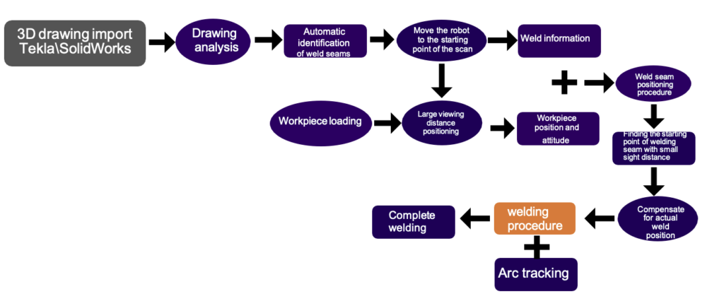
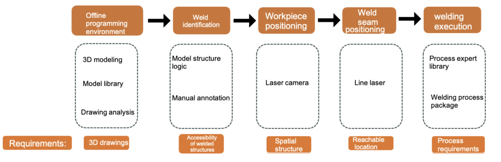
Import 3D models or drawings from mainstream structural design software, identify the required weld features and prepare the robot trajectory away from the production cell. Parametric modeling helps organize repeatable part families, while the digital-twin view gives engineers a way to inspect robot posture, torch access and coordinated motion before release. This route is especially valuable when engineering data is available early and the fabricator wants programming work to happen in parallel with fixture and material preparation.
Offline preparation is not only a drawing-conversion step. The proposed path must be associated with the intended joint, welding sequence and process recipe. EVST combines trajectory planning with a process expert library so that path data and welding parameters can be prepared as one job package for review. That package can then be aligned to the real workpiece through the vision layer at the cell.
Batch Weld Generation from 3D Models
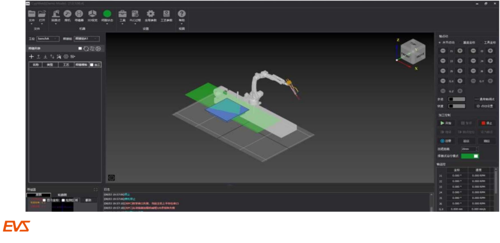
From an approved 3D model, automatic weld seam recognition identifies candidate features; automatic weld seam generation from the 3D model organizes a reviewable offline job.
How does batch weld generation work? Compared with manual teaching, engineers review joints, access, sequence and recipe before release. Recognition proposes work; it does not approve.
3D line scanning is also supported
When usable model data is unavailable or the real workpiece needs to be captured in the cell, the system can scan the relevant geometry, extract a workpiece model and locate weld information from the scan. This additional route gives fabricators a second way to create the job around part variation, fixture repeatability and weld access.
After the workpiece is located, laser seam tracking supports the robot during welding by relating torch motion to the detected seam. It connects planned geometry with the actual seam condition as one layer within the robot motion, welding power, torch, fixture and operator-control architecture.
From Workpiece Data to a Controlled Welding Job
The following workflow shows where automation acts and where engineering confirmation remains essential.
Prepare the workpiece definition
Start from an approved model or drawing, or plan a scan when the real geometry must be captured. Define the welds that belong to the job and confirm that the fixture provides the required access.
Locate the real part
Use 3D vision positioning to align the job with the workpiece in the cell. The vision result connects the prepared trajectory to the actual placement rather than assuming that digital and physical coordinates already match.
Generate and review the trajectory
Create the welding path, inspect robot posture and coordinated-axis motion in the digital-twin environment, and associate the selected process recipe. Collision detection supports this review before the job is released.
Execute with process support
Run the confirmed job with the configured welding source, torch and optional seam-tracking layer. Continuous welding, fillet welding and multi-layer or multi-pass strategies can be organized according to the approved application package.
Recover and manage the job
Breakpoint recovery supports a controlled return after an interruption. Parametric models and the process expert library help the team manage related workpiece families without rebuilding every job from an empty program.
System Architecture for Structural Steel Cells
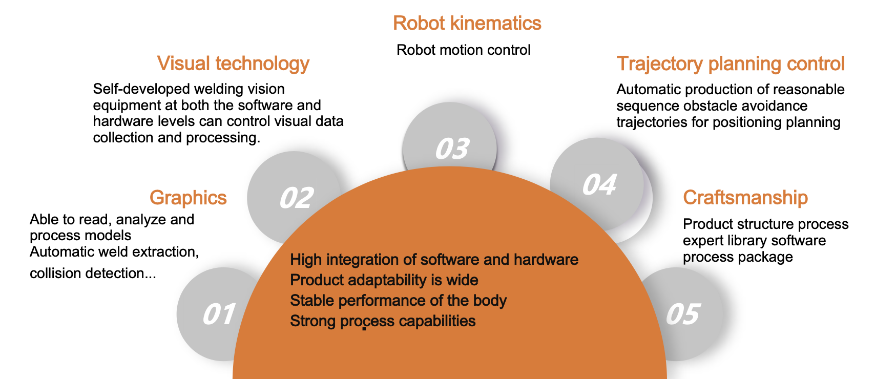
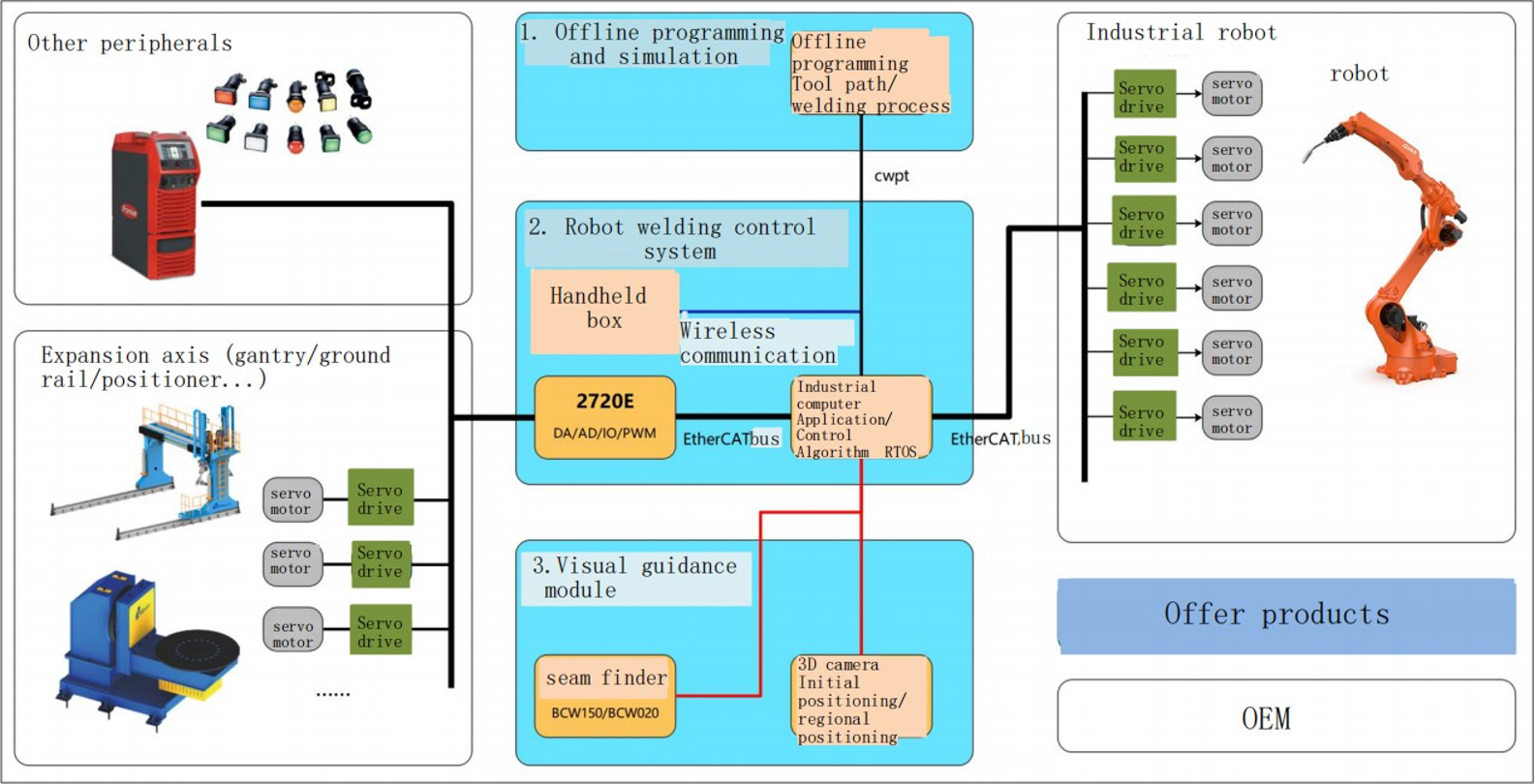
An intelligent welding result comes from the coordinated cell, not from a robot arm alone. EVST configures the software, sensing, robot, welding package and external axes around the workpiece and production method.
| Cell layer | Role in the welding workflow | Configuration notes |
|---|---|---|
| Planning and control | Offline programming, trajectory generation, digital twin, parametric modeling, process expert library and job management. | Model or drawing import is the primary planning route; 3D line scanning is also supported. |
| Vision and sensing | 3D vision positioning locates the workpiece; laser seam tracking can support the approved weld during execution. | Sensor selection and mounting depend on joint access, surface condition and cell layout. |
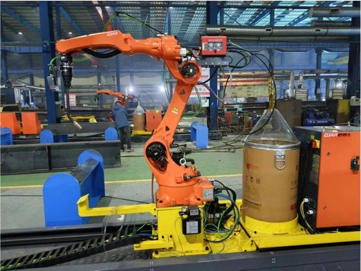
| Welding robots | QJR6-1400H or QJR6-2000H provides the welding motion platform. | Select reach from the workpiece envelope, torch access, fixture position and external-axis arrangement. |
| External axes | Rail and positioner motion expands access and coordinates the workpiece with the robot. | The current architecture supports a 3+2 external-axis arrangement. |
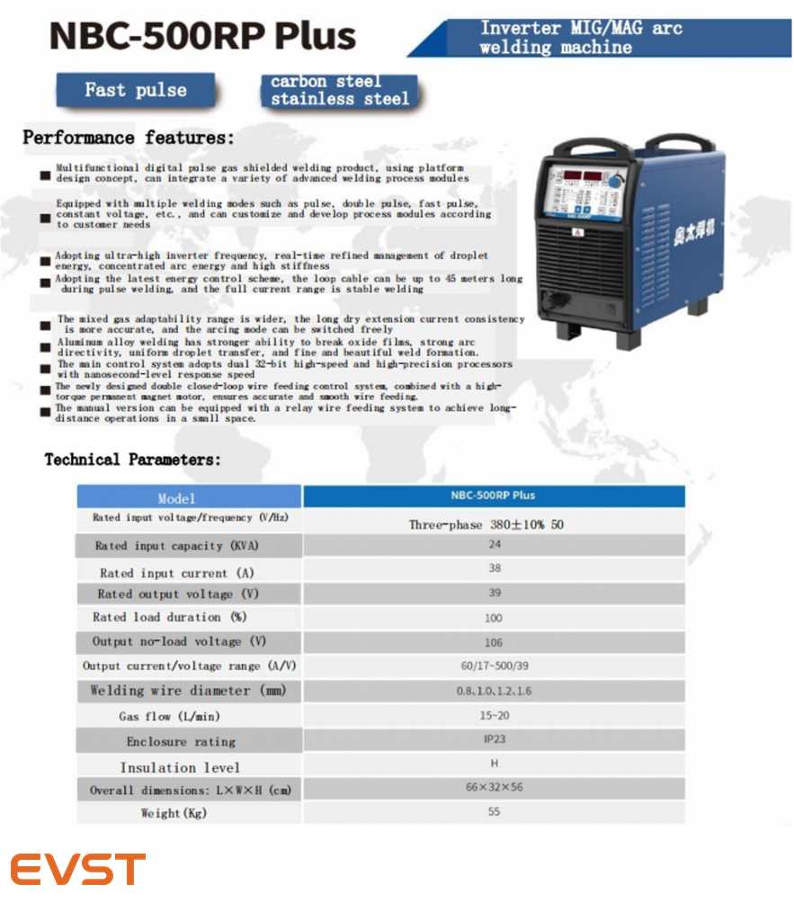
| Welding package | The power source, wire delivery, torch, cooling and process configuration create the arc package. | The system can be configured with either the Aotai NBC500RP Plus or the Megmeet Dex2 500MPR welding power source. |
| Cell support | A gun cleaning station supports torch maintenance within the planned cell workflow. | Fixture, guarding, extraction and operator access are finalized for the actual installation. |
Control system coordination
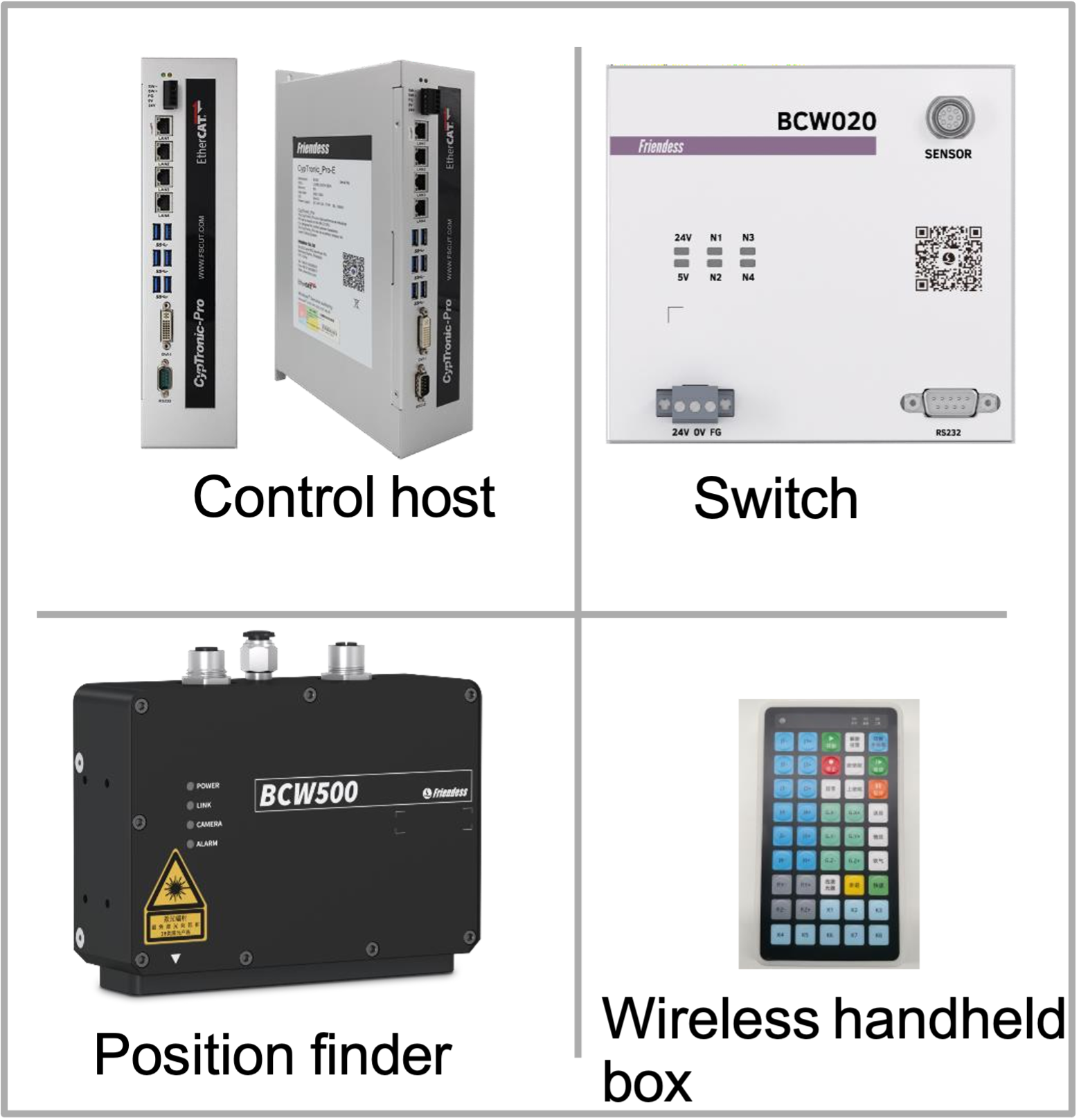
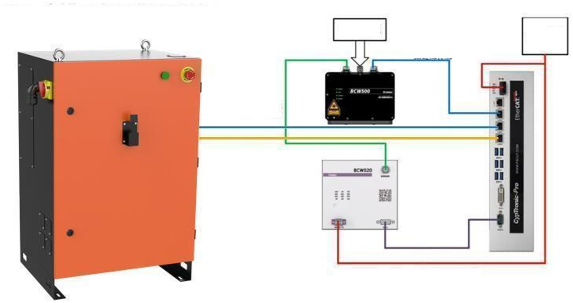
The control system coordinates planning, robot motion, sensing, welding execution and job management; project-specific module detail is confirmed against the selected cell architecture.
Seven-Axis and Eight-Axis Layout Options
EVST combines robot reach with rail travel and workpiece presentation so the cell can follow long members, preserve torch access and organize loading around the structural assembly.
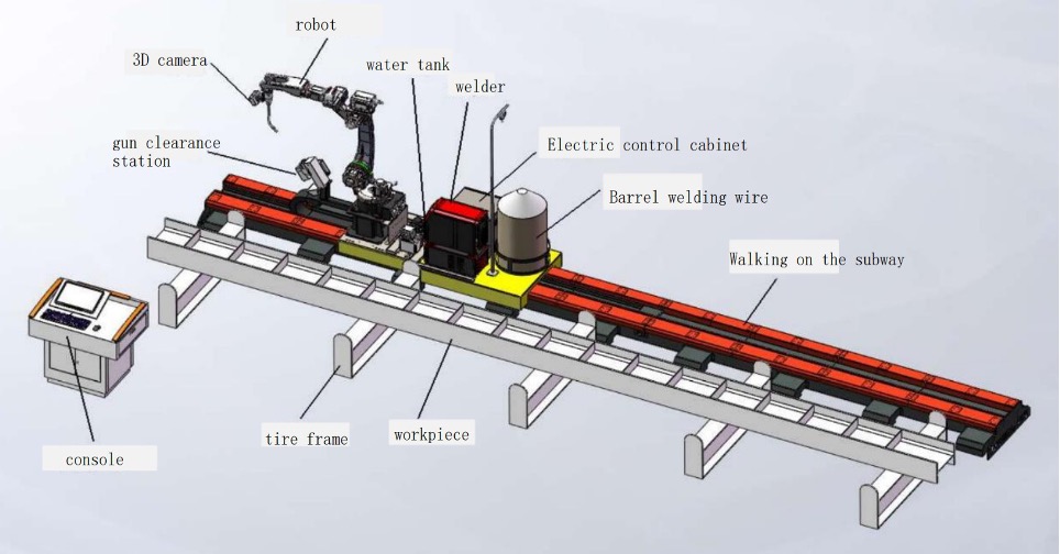
Seven-axis upright rail
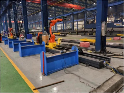
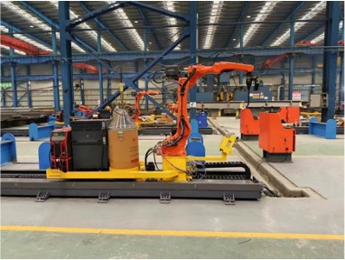
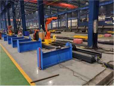
A floor-mounted robot rail beside the fixture provides direct service access and extends coverage along beams, frames and open structural assemblies.
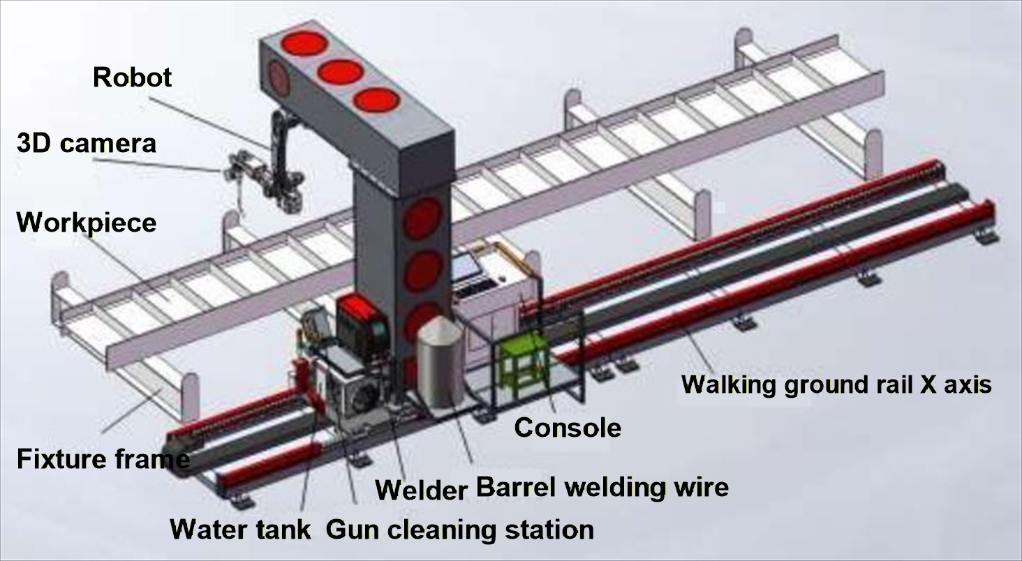
Seven-axis inverted rail
An overhead or inverted robot rail opens the floor around larger fixtures and workpieces while preserving travel along the weld envelope.
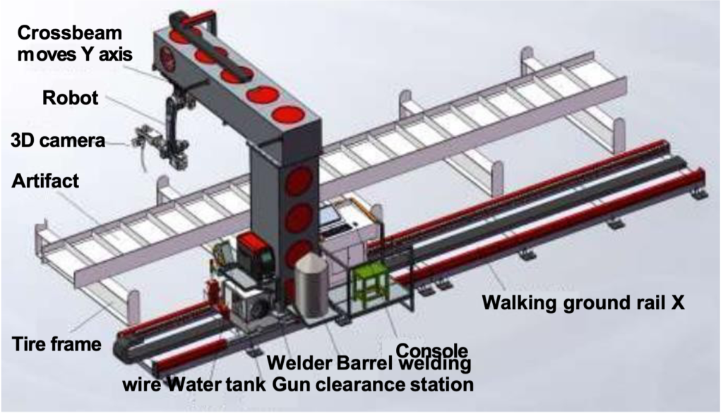
Eight-axis coordinated layout
An additional coordinated axis expands workpiece orientation or robot coverage for assemblies with welds distributed across multiple faces.
| Layout | Typical workpiece pattern | Footprint and loading approach | Choose this layout when |
|---|---|---|---|
| Seven-axis upright rail | Long beams, frames and open-sided structural assemblies | Floor rail runs beside the fixture with direct floor-level loading and service access. | Top and side welds are accessible and a straightforward ground-rail cell fits the available floor plan. |
| Seven-axis inverted rail | Large tanks, cabinets and long members that benefit from an open floor | Robot travel is carried above the work zone, leaving more floor space around the fixture and loading path. | Overhead access improves torch approach or keeps ground-level material handling clear. |
| Eight-axis coordinated layout | Complex assemblies with welds across multiple faces or changing orientations | The added coordinated axis extends orientation or coverage around the workpiece. | The required weld envelope cannot be covered efficiently by seven-axis travel alone. |
Robot and external-axis selection
Robot selection starts with the weld envelope and torch approach, then considers how the rail or positioner presents each joint. EVST compares robot posture, cable routing, torch clearance, fixture zones and coordinated motion around the actual workpiece family.
| Configuration item | Published value | Application role |
|---|---|---|
| QJR6-1400H welding robot | 6 kg payload; 1456 mm arm span | Compact structural steel cells and layouts where the fixture brings joints within the shorter reach envelope. |
| QJR6-2000H welding robot | 6 kg payload; 2014 mm arm span | Longer-reach layouts where the robot must access a wider workpiece envelope. |
| Coordinated external axes | 3+2 | Combines travel and workpiece positioning axes around the robot welding task. |
| Rail load reference | 500 kg upright; 2 T inverted | Provides a planning reference for upright or inverted rail arrangements in the current solution architecture. |
Scope of Supply
The current EVST configuration sheet separates the core intelligent welding package from optional equipment and items supplied at project level.
| Item | Proposed component | Supply status | Notes |
|---|---|---|---|
| Robot body | QJR6-1400H or QJR6-2000H intelligent welding version | Included | Choose robot reach around the weld envelope and torch access. |
| Welding machine and wire-feeding system | Aotai NBC500RP Plus or Megmeet Dex2 500MPR | Included | Power-source option is selected with the welding process package. |
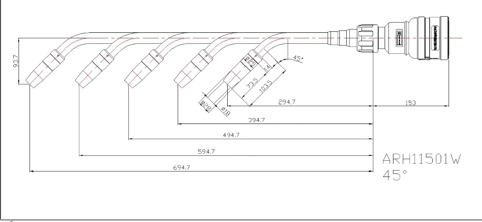
| Water-cooled welding torch | Arctec ARH11501W | Included | Standard length 294.7 with +100L, +200L and +300L variants. |
| Intelligent welding system | Laser, industrial computer and control system | Included | Provides the planning, positioning and intelligent welding control layer. |
| External-axis control | 3+2 expansion-axis control | Project-defined | Defined in the project proposal according to the selected layout. |
| Gun cleaning station | Three-in-one cleaning, cutting and oiling station | Optional | Supports routine torch service inside the planned cell workflow. |
| Operation desk and control cabinet | Mouse, keyboard, display, industrial-computer installation and switch | Not included | Listed as customer- or project-supplied on the current configuration sheet. |
| Ground rail and L-shaped inverted-beam slide | Upright or inverted rail and robot-carrying slide | Not included | Current references: 500 kg upright rail or 2 T inverted rail; slide carries the robot and associated cell equipment. |
| Fixture frame or workpiece platform | Workpiece support | Not included | Designed around the actual structural workpiece and loading method. |
Final scope of supply is confirmed in the project proposal.
Working with EVST as Your Intelligent Welding System Supplier
When comparing intelligent welding system manufacturers in China, review responsibility for planning, sensing, integration, coordination and delivery. EVST approaches each project as a China-based supplier and integrator, with the proposed scope built around the workpiece and acceptance plan.
Suppliers set different boundaries. An OEM supplier typically defines branding, documentation, site services and acceptance before equipment is selected. Buyers should distinguish included, optional and project-defined items rather than treating a system offered for sale as a fixed package.
To request a quote, provide workpiece and joint data, expected variation, fixture and loading concepts, cell space and site-service requirements. Overseas delivery, installation, commissioning, training and documentation are reviewed as project-scope items and included only when confirmed in the proposal.
Welding Functions Available to the Application Engineer
The EVST software layer brings together offline programming, 3D model import, 3D vision positioning, automatic trajectory planning, digital-twin review, parametric modeling and collision detection. During welding, the configured cell can use laser seam tracking, continuous or fillet welding strategies, multi-layer and multi-pass planning, breakpoint recovery and recipes from the process expert library. EVST selects the relevant functions as one application package for the workpiece and welding procedure.
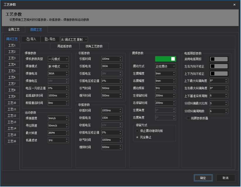
For suitable medium-to-thick plate applications, the current materials describe a critical-pulse option with travel speed stated as 1.2–1.5× standard pulse. EVST evaluates the power source, base material, filler, joint design, shielding and heat input together during process development.
The practical value of the software is the way these functions connect. A parametric part definition can feed path generation; the digital twin can expose a posture or collision concern; vision can align the approved job with the physical part; tracking can support execution; and breakpoint recovery can return an interrupted job to a controlled state. This connected sequence is the basis of the EVST teach-free proposition.
Process-parameter library
The process-parameter library keeps approved welding recipes available for job preparation, while applicable settings remain subject to workpiece, joint and welding-procedure validation.
Structural Steel Application Examples
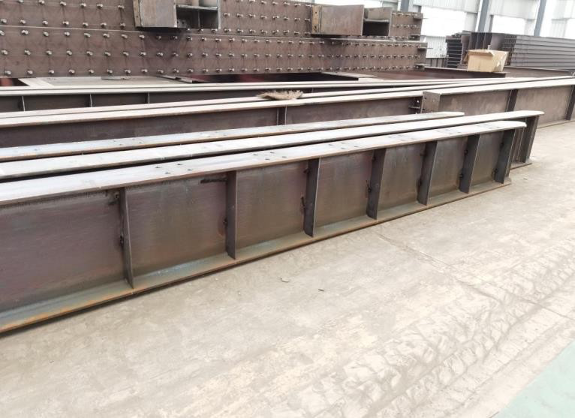
The current EVST page presents four representative structural workpieces. Together they show how offline planning, vision alignment and coordinated motion address different joint-access patterns.
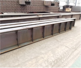
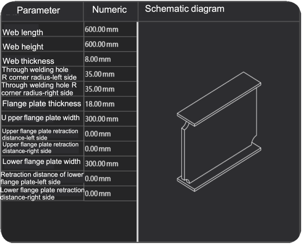
H-shaped structural stiffener welding
Repeated stiffener joints reward model-based path preparation and consistent fixture references. The application review focuses on torch approach, joint sequence and how the robot reaches both sides of the connected plate features.
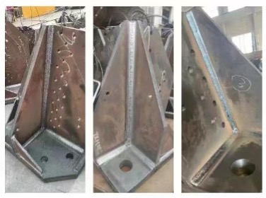
Tower corner welding
Tower corner geometry brings several weld orientations into a compact area. The cell concept must coordinate part presentation, torch clearance and an ordered path that the application engineer can review before production.
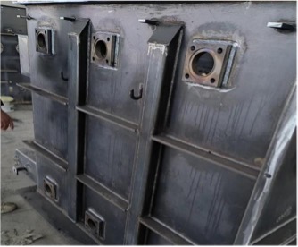
Transformer tank welding
Large panels and attached structural features require a layout that keeps the weld envelope, fixtures and robot posture visible as one system. EVST also documents a dedicated transformer tank welding solution for readers evaluating this workpiece family.
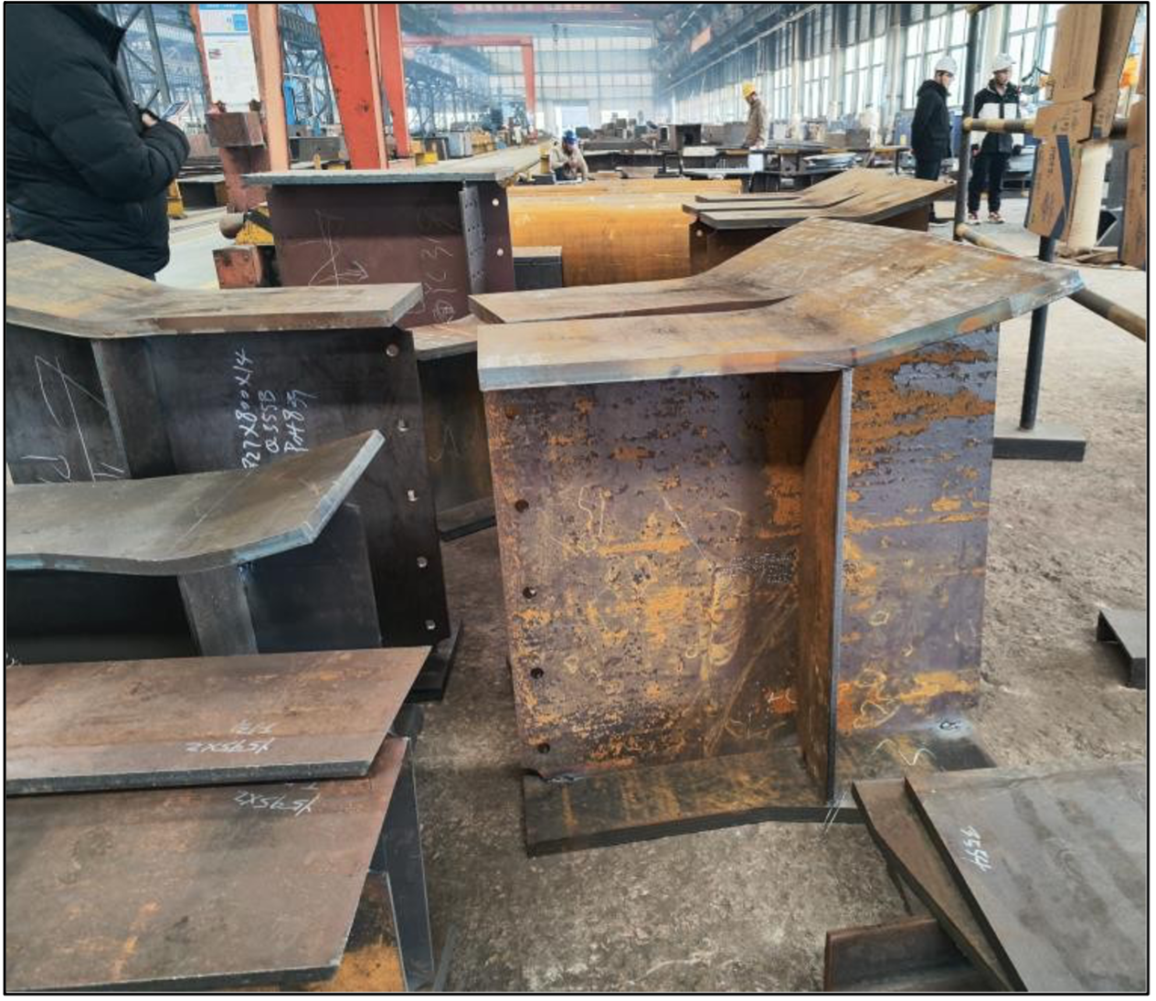
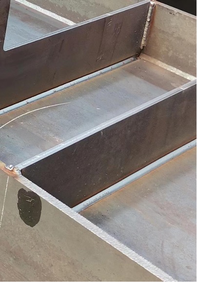
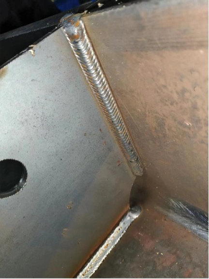
Corbel welding
Corbels combine short intersecting joints with restricted approach angles. Offline trajectory preparation and a clear fixture reference help the engineer test access and sequence before releasing the job to the cell.
How to Evaluate Whether the System Fits Your Workpieces
A useful evaluation starts with representative workpiece information rather than a generic robot request. Share the available model or drawing, the joints to be welded, material and filler information, expected part-family variation, fixture concept, preferred loading method and the space available around the cell. If engineering data is incomplete, identify which surfaces and weld regions can be scanned and how the real part will be presented.
EVST can then compare the model-based and scan-based routes, review QJR6-1400H and QJR6-2000H reach, consider rail or positioner motion, and identify the welding source and torch package that should enter process testing. The review should also identify operator access, consumable service, gun cleaning, fume extraction, guarding and recovery from an interrupted job. Those items influence the usable cell even though they do not appear in a robot payload table.
Before production release, the application team should confirm the selected path, process recipe, workpiece location method and cell operating sequence using the agreed samples. This is also the point to define which settings an operator may select, which changes require welding-engineering approval and what information must be retained with each job. Teach-free path creation is most effective when those responsibilities are explicit.
Intelligent welding system vs traditional welding robot
An equipment selection guide should compare the engineering route, not robot specifications alone. The distinction between an integrated system and a robotic welding cell also asks how workpiece data becomes an approved job.
| Evaluation point | Traditional welding robot | Integrated welding system | Confirm before selection |
|---|---|---|---|
| Path creation | Point teaching or a separate robot program | Model- or scan-based path preparation and review | Data quality, recognition and approval responsibility |
| Cell responsibility | Robot motion may be one supplied layer | Planning, sensing, welding, external axes and job management are coordinated | Equipment, interfaces, guarding and site services |
Intelligent welding system requirements checklist
- Models or drawings and defined weld joints
- Material, filler and welding procedure
- Workpiece variation and fixture repeatability
- Reach, torch access, external axes and cell space
- Loading, safety, service and recovery
- Validation, acceptance and change ownership
Choosing the right configuration is a fit decision. A pros-and-cons review weighs less repetitive path preparation against controlled data, fixtures and process approval. A small workshop needs workable loading and support; high-mix, low-volume production needs controlled part families.
Related EVST Robots, Cells and Positioning Equipment
Explore focused guides for teach-free operation, structural-steel applications and workstation fundamentals, then review the related product resources.
See the Intelligent Welding Workflow
These two verified EVST official-channel videos demonstrate programming reduction and intelligent welding on structural steel workpieces.
No Programming Needed: Smart Welding Robot
EVST official-channel demonstration of a smart welding robot workflow that reduces manual programming.
Intelligent Welding System for Steel Structures
EVST official-channel view of an intelligent welding system applied to structural steel workpieces.
What Determines the Cost of an Intelligent Welding Workstation
How much does an intelligent welding workstation cost? A useful price range depends on the workpiece, sensing route, robot, external axes, welding package, fixtures and acceptance scope.
| Cost driver | What changes the scope |
|---|---|
| Workpiece and job preparation | Model or scan route, joint count and part variation |
| Cell hardware | Robot reach, external axes, sensing, welding and support equipment |
| Integration and validation | Fixture and safety interfaces, sample validation and acceptance |
| Delivery and ownership | Installation, training, documentation, maintenance and change control |
To estimate intelligent welding workstation ROI, compare programming labor, cycle time, rework and interruptions across the same workpiece mix and period. Use verified differences to compare the automated cell with manual welding and calculate a payback period.
Intelligent welding workstation total cost of ownership also includes fixtures, utilities, consumables, maintenance, training and future changes. Whether the investment is worthwhile depends on verified savings and production control, not a generic price claim.
Frequently Asked Questions
What does teach-free welding mean in this EVST system?
It means the robot path is prepared from approved workpiece data or captured geometry instead of manual point-by-point teach-pendant programming. The workflow concentrates operator and welding-engineer effort on approving the job rather than teaching every point.
Can the system import models or drawings?
Yes. The primary workflow imports 3D models or drawings from mainstream structural design software, identifies weld features and prepares robot trajectories offline. The resulting job combines geometry, path and process information for cell alignment and execution.
Can EVST work when usable model data is not available?
The system also supports a 3D line-scan route that captures relevant workpiece geometry and extracts weld information. Use this route when part geometry must be captured at the cell and the workpiece offers suitable scanning access.
What is the difference between 3D vision positioning and laser seam tracking?
3D vision positioning aligns the prepared job with the physical workpiece in the cell. Laser seam tracking supports the robot during execution by relating torch motion to the detected seam. They serve different stages of the workflow.
Can one operator run the system? What skills are required?
A trained operator can run the commissioned workflow. The operator loads the approved job, confirms the workpiece and fixture, and follows the cell sequence; a welding engineer remains responsible for welding-procedure selection, process validation and approval of changes.
Does the system support multi-layer and multi-pass welding?
Yes. For suitable medium-to-thick plate applications, multi-layer and multi-pass welding can use the documented critical-pulse mode, with travel speed stated as 1.2–1.5× standard pulse. Pass planning comes from the welding process expert library and is confirmed against the approved welding procedure.
What information should be prepared for a solution review?
Prepare representative models or drawings, weld-joint information, material and filler details, expected part-family variation, fixture concept, loading method and available cell space. If a scan-based route is being considered, also identify the surfaces and weld regions that can be captured.
What does a typical project look like from order to production? Is installation and training included?
Installation and operator training can be included in the agreed project scope. A typical project moves from solution evaluation and sample process validation through manufacturing and integration, on-site installation and commissioning, operator training, production handover and after-sales support. The final commercial proposal defines the supplied services.
Can the system work with our existing welding power source?
Possibly, subject to project evaluation. Standard options are Aotai NBC500RP Plus and Megmeet Dex2 500MPR. For an existing or other-brand power source, EVST evaluates communication compatibility and welding-process fit before confirming the configuration; no third-party brand is assumed compatible in advance.
Build the Cell Around the Workpiece
A teach-free welding project begins with the workpiece family, weld access and available engineering data. EVST can use that information to review the planning route, robot reach, external axes, welding package and confirmation workflow as one solution. The same evidence defines the supplier boundary and makes the cost and ROI review specific to the application. For a configuration review, share representative application information through the EVST solution evaluation contact page.
Contact Us