
Welding Robot Workstation Configurations: Cells, Rail and Gantry Systems
A welding robot workstation combines robots, welding equipment, workpiece handling, fixtures, controls and safeguards around a defined production need. This selection hub compares four configuration families and routes application-specific detail to dedicated pages. Use the in-page links to move from workpiece constraints to a suitable architecture.
Start by placing the application in one of four families
Each category card uses the same fields to identify a selection route. Numeric values and engineering conditions stay in the relevant sections below.
Light and medium cells
- Starting fit
- Repeatable light and medium part families
- Defining motion
- Local flip, rotary or multi-axis positioning
- Next review
- Continue to the light-configuration route
Large and high-load stations
- Starting fit
- Long, large-envelope or high-mass workpieces
- Defining motion
- High-load positioning and extended robot reach
- Next review
- Continue to the large-part engineering route
Ground, sky-rail and gantry systems
- Starting fit
- Long, wide or tall zones beyond one fixed robot position
- Defining motion
- Robot travel on linear external axes
- Next review
- Compare four mobile-system architectures
Positioners and fixtures
- Starting fit
- Parts requiring stable orientation and repeatable locating
- Defining motion
- Move the part and hold joint relationships
- Next review
- Review workpiece-motion and holding boundaries
Four constraints determine the most useful starting route
Begin with the workpiece envelope and length, then include the combined workpiece-and-fixture load in the positioning calculation. Next define the motion axes and robot coverage needed across the seam map. Finally, narrow the architecture by welding process and joint form; the configuration name is only a starting point for project confirmation.
Envelope and length
Decide whether one fixed robot location can cover every required seam.
Positioning load
Treat the workpiece, fixture and dynamic orientation as one load problem.
Motion axes
Distinguish moving the part, moving the robot or combining external axes.
Applicable welding process
Screen the joint and equipment boundary for gas-shielded, argon arc or laser welding.
Enclosed configurations for repeatable part families
When the workpiece envelope and load fit local flipping, horizontal rotation, multi-axis positioning or headstock-tailstock support, begin with a cell-level configuration. The dedicated page compares six arrangements while keeping fixture, robot quantity and safeguarding decisions project-specific.
robotic welding cell configurations for light and medium workpieces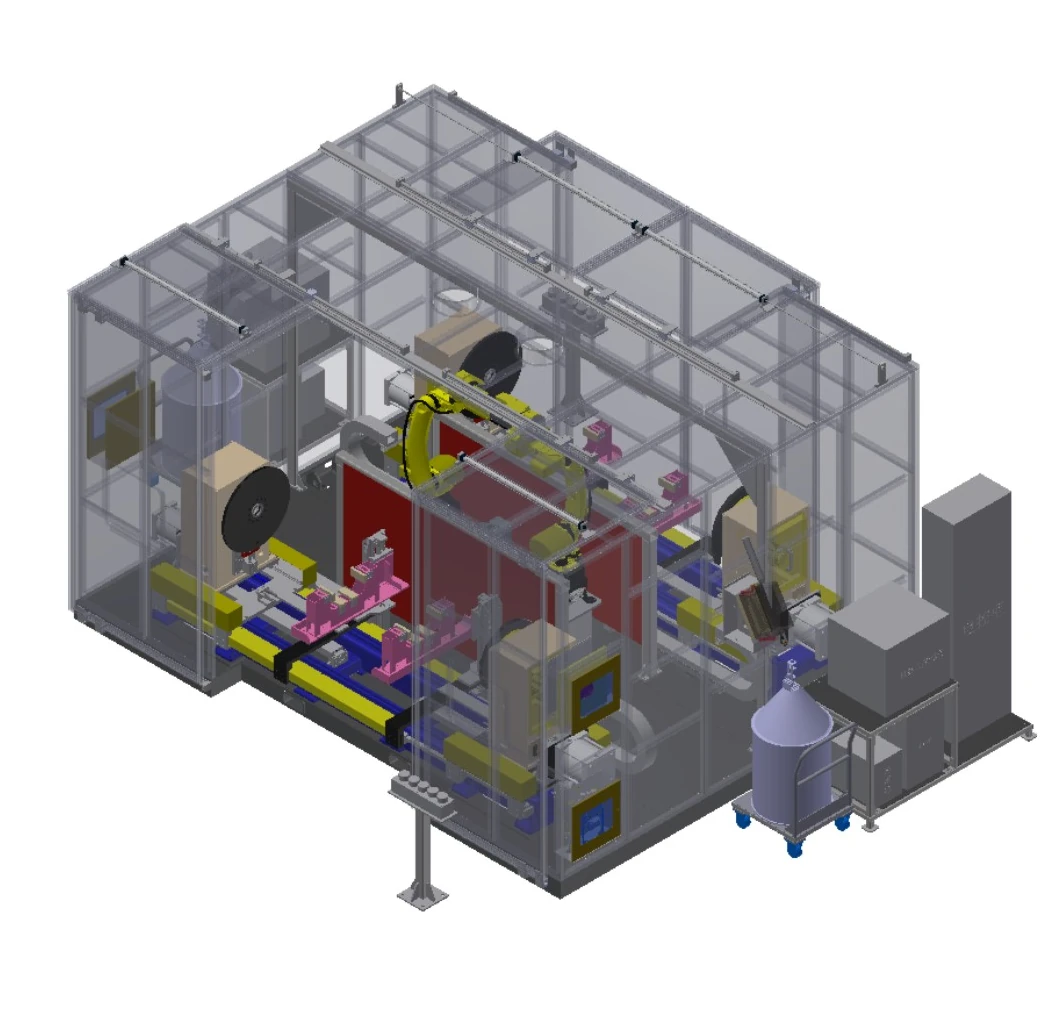
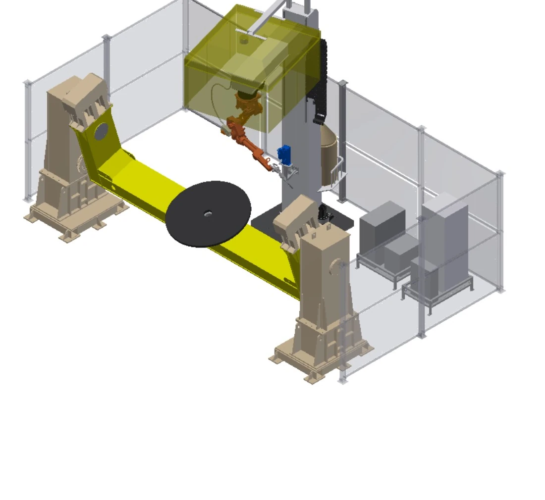
Engineered stations for long, large or high-mass parts
When length, mass, rotation diameter or loading method exceeds a conventional cell envelope, start from support, positioning, external motion and protection constraints. The dedicated page presents eight engineering starting points rather than fixed equipment packages.
heavy duty welding robot workstations for large and heavy partsFour ground-rail, sky-rail and gantry architectures
When one fixed robot position cannot cover the required length, height or span, linear external axes carry the robot to the seam zone. These four architectures address upright floor travel, inverted floor travel, multi-axis overhead travel and wide gantry coverage.
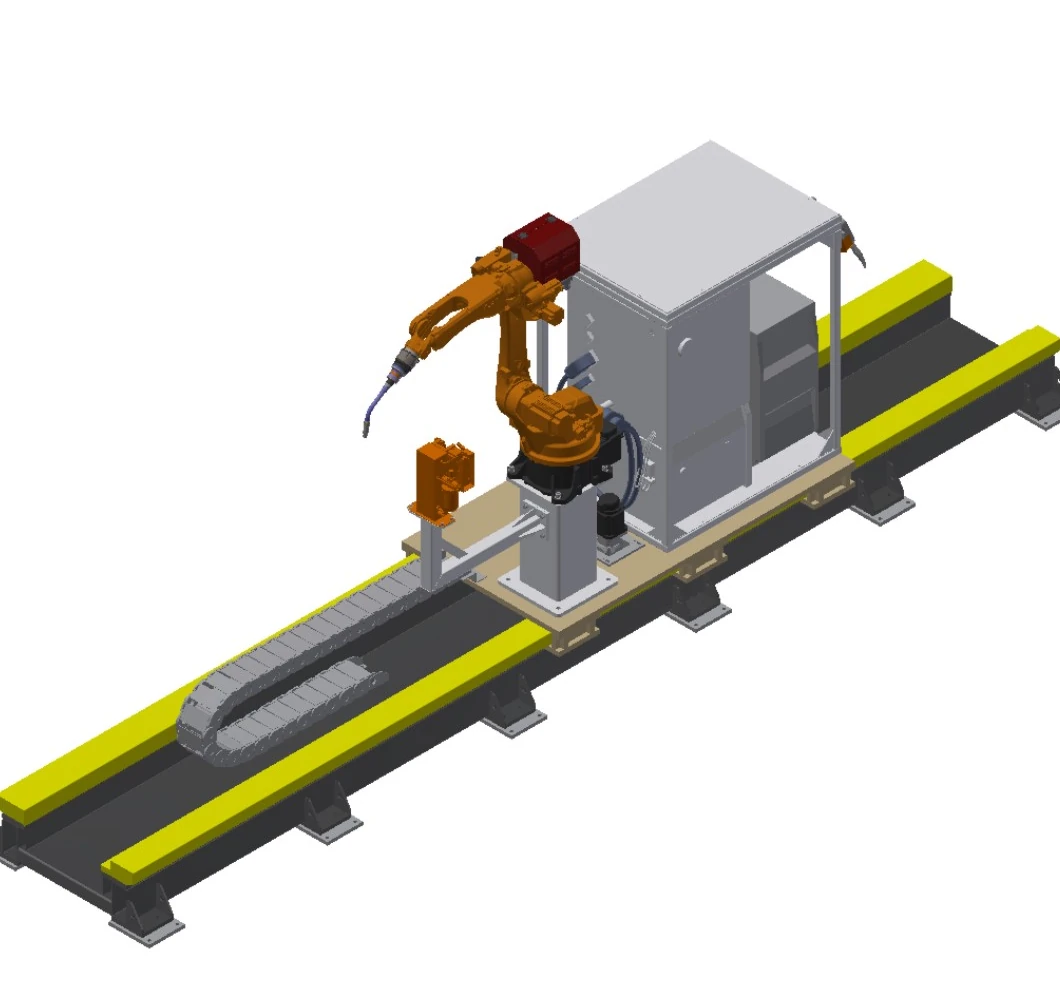
Upright Ground-Rail Welding System
Extends robot coverage along long workpieces while keeping the robot upright on a floor-mounted carriage.
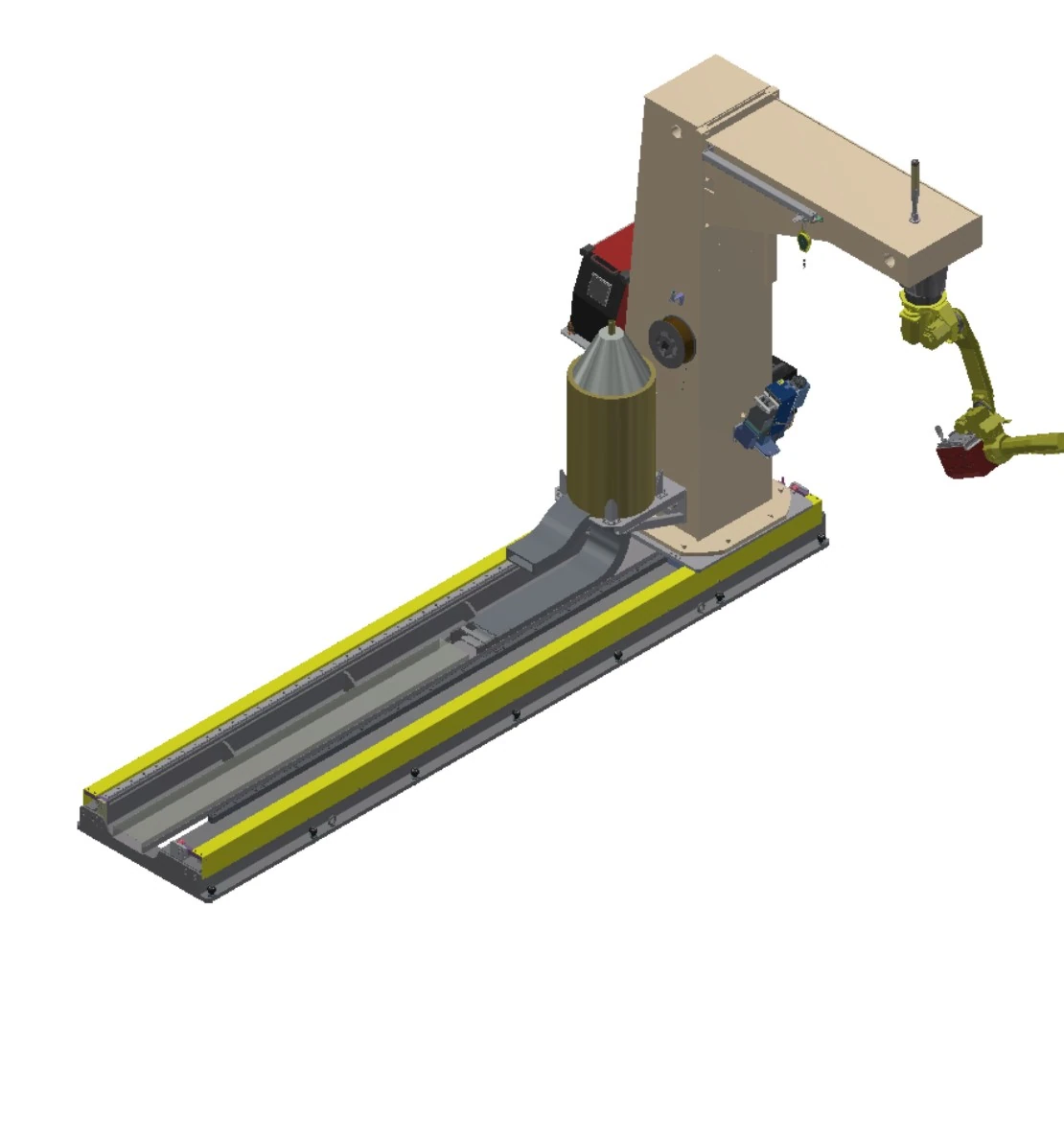
Inverted Ground-Rail Welding System
Combines floor travel with an inverted C-frame when overhead access is useful along a long workpiece.
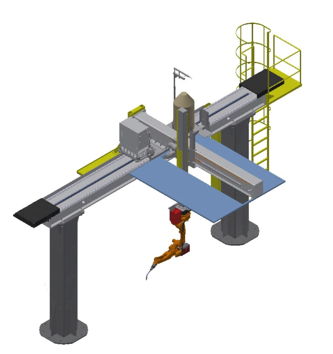
Inverted Sky-Rail Welding System
Moves an inverted robot above the work zone in selectable axis combinations for length, lateral reach and height.
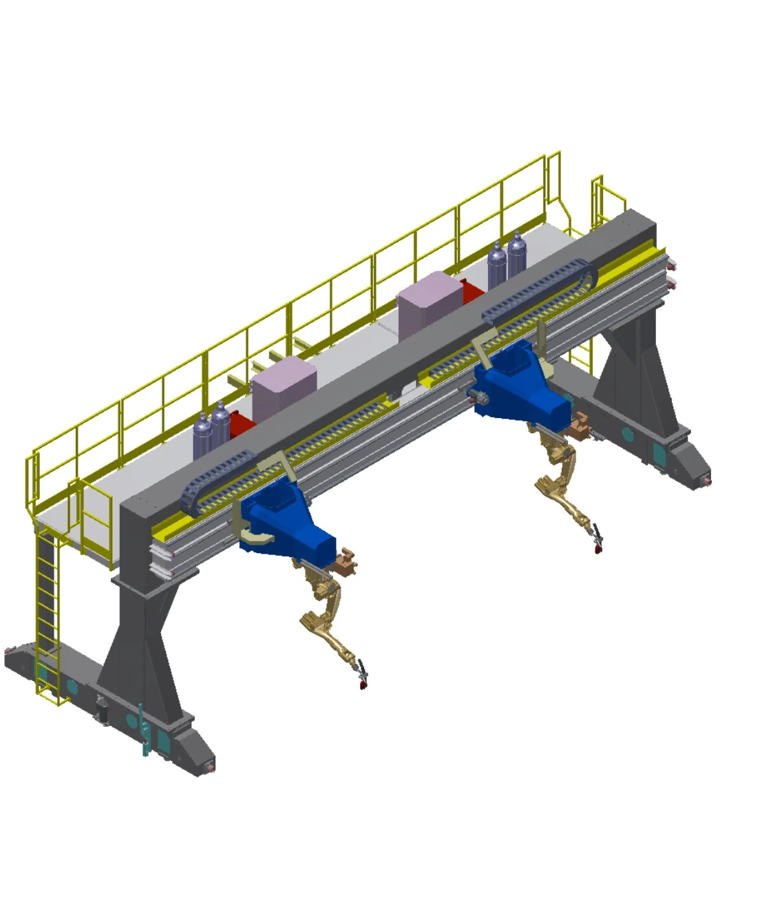
Inverted Gantry Welding System
Creates a wide overhead envelope with long Y travel and synchronized dual drive for large work zones.
Compare four mobile systems on one set of fields
Travel values are optional ranges. Final axis combination, load, foundation, process software and tracking scope remain project-specific.
| Row | System | Motion | Travel | Rated load | Speed | Repeatability | External axes | Options and engineering conditions |
|---|---|---|---|---|---|---|---|---|
| A | Upright Ground-Rail Welding System | Ground rail; one linear external axis | Effective travel 2–30 m, optional | 1 t | 0–15 m/min | ±0.15 mm | 1 set | Robot base and brackets for controls, welding equipment, wire drum and torch cleaner; extended flexible cable; contact sensing, arc tracking and multilayer multipass software; laser seam tracking |
| B | Inverted Ground-Rail Welding System | Heavy ground rail with inverted C-frame; one linear external axis | Effective travel 2–30 m, optional | 3.5 t | 0–15 m/min | ±0.15 mm | 1 set | Inverted C-frame with robot base and brackets for controls, welding equipment, wire drum and torch cleaner; extended flexible cable; contact sensing, arc tracking and multilayer multipass software; laser seam tracking |
| C | Inverted Sky-Rail Welding System | Overhead X/Y/Z travel; axes may be combined as 1X, 2Y or 3Z | X 2–30 m; Y 1–2 m; Z 1–2 m, optional | 0.4 t | Each axis 0–15 m/min | Each axis ±0.15 mm | 3 sets | Brackets for controls, welding equipment, wire drum and torch cleaner; inspection ladder and platform; extended flexible cable; optional ceiling fume hood; contact sensing, arc tracking and multilayer multipass software; laser seam tracking |
| D | Inverted Gantry Welding System | Gantry X/Y/Z travel; axes may be combined as 1X, 2Y or 3Z; synchronous dual drive on Y | Span <10 m; X ≤9 m; Y ≤100 m; Z 1–2 m, optional | 0.4 t per robot | Each axis 0–15 m/min | Each axis ±0.15 mm | 4 sets | P43 precision-ground heavy rail and project foundation by user; brackets for controls, welding equipment, wire drum and torch cleaner; inspection ladder and platform; extended flexible cable; contact sensing, arc tracking and multilayer multipass software; laser seam tracking |
Treat positioners and fixtures as one workpiece chain
The positioner presents each joint at a weldable orientation; the fixture locates the components and repeatedly preserves their relationship. Both must be confirmed with robot access, weld sequence, loading and safeguarding.
Positioning concepts
Screen fixed tables, horizontal rotary tables, flip units, headstock-tailstock support and multi-axis positioners. Combined workpiece-and-fixture mass, centre of gravity, rotational envelope and torch clearance define the applicable concept.
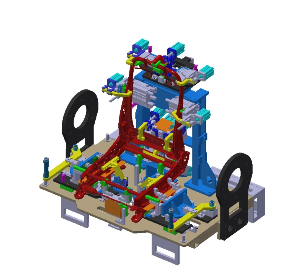
Fixture engineering
Quick-change design can preserve an interface for product updates. Structural frames require sufficient stiffness and strength, welded structures undergo ageing treatment, and each component is located and clamped independently to maintain drawing relationships.
Use four questions to define the next engineering sketch
How large is the part?
Provide minimum and maximum envelope, length, loading direction and seam distribution.
What load must move?
Combine workpiece and fixture mass, then add centre of gravity and dynamic orientation.
Which axes are needed?
Decide whether to move the part, move the robot, or use ground rail, sky rail or gantry travel.
Which process applies?
Share material, joints, welding method, quality requirements and changeover pattern.
When the scope expands to line takt, cross-station handoffs and system-level orchestration, continue to the intelligent welding production line.
Choose which family to review first
Which category fits small or medium repeat parts?
Start with light and medium enclosed cells, then narrow the route by flip, rotary or multi-axis part positioning.
Which category fits long, large-envelope or high-load parts?
Start with the large-workpiece engineering route and provide mass, centre of gravity, support, loading and seam-distribution data.
When should I compare ground rail, sky rail or gantry systems?
Use the mobile-system comparison when one fixed robot location cannot cover the required length, height or span.
Where do complex workholding and fixture questions belong?
When orientation, repeatable locating or change interfaces are the main constraint, begin with the positioners and fixtures section.
Move from the application family to the next information layer
Use this page to select a configuration family, then open the relevant product or technical page. If drawings are ready, begin an application discussion directly.
Start from the real part and seam map
Share drawings, size and mass range, joints, process, takt expectation, loading method and site constraints so EVST can frame an initial configuration.